Power supplying system, monitoring apparatus, monitoring method and computer program

Active Publication Date: 2009-08-20
SONY CORP
View PDF19 Cites 25 Cited by
  • Summary
  • Abstract
  • Description
  • Claims
  • Application Information

AI Technical Summary

Benefits of technology

[0021]According to the embodiments of the present invention described above, it is possible to provide a power supplyin

Problems solved by technology

However, there is no means of monitoring the operation state.
Further, if an information signal which represents information and power which serves as energy are

Method used


Image

  • Power supplying system, monitoring apparatus, monitoring method and computer program
  • Power supplying system, monitoring apparatus, monitoring method and computer program
  • Power supplying system, monitoring apparatus, monitoring method and computer program

Examples


first embodiment

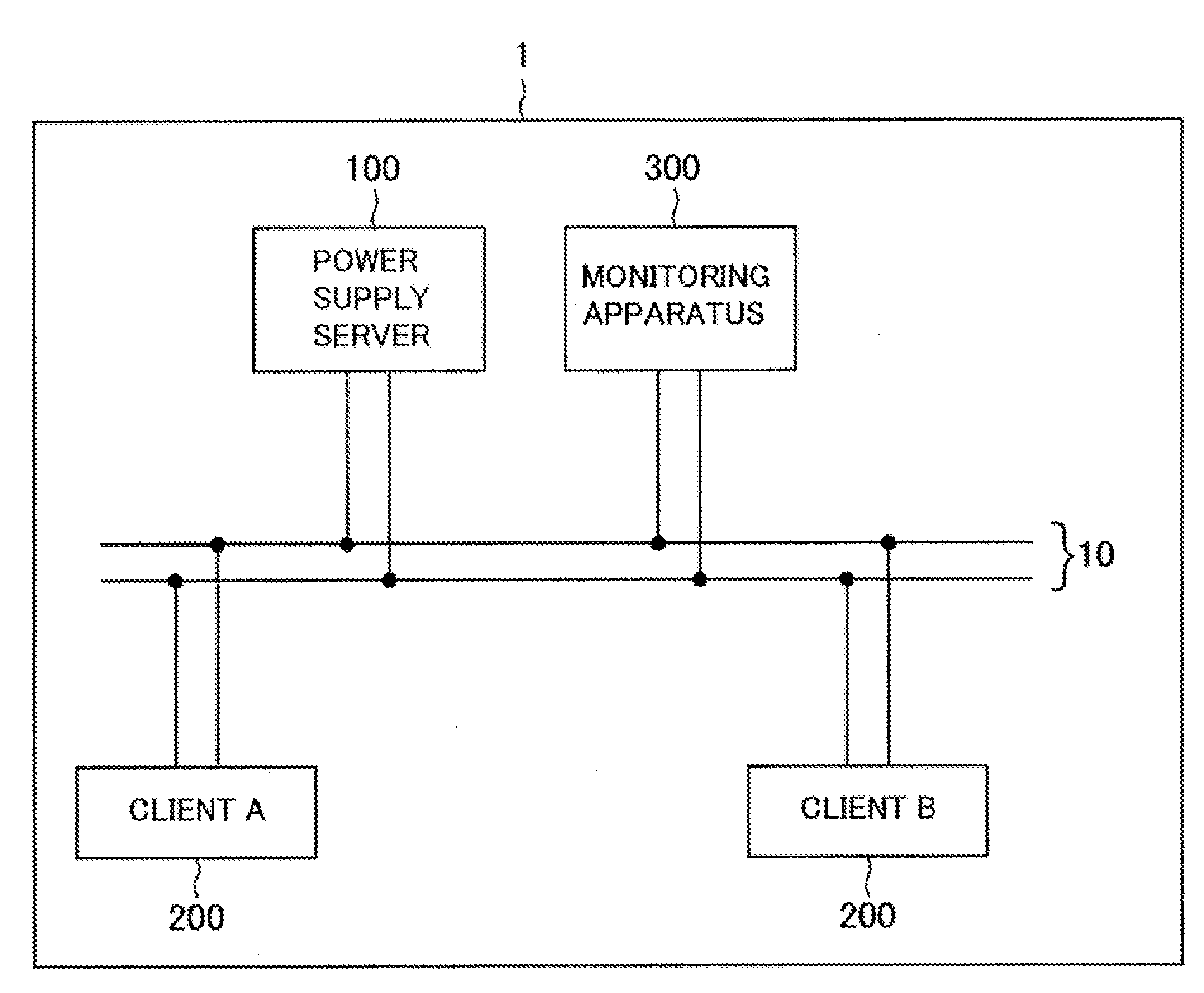
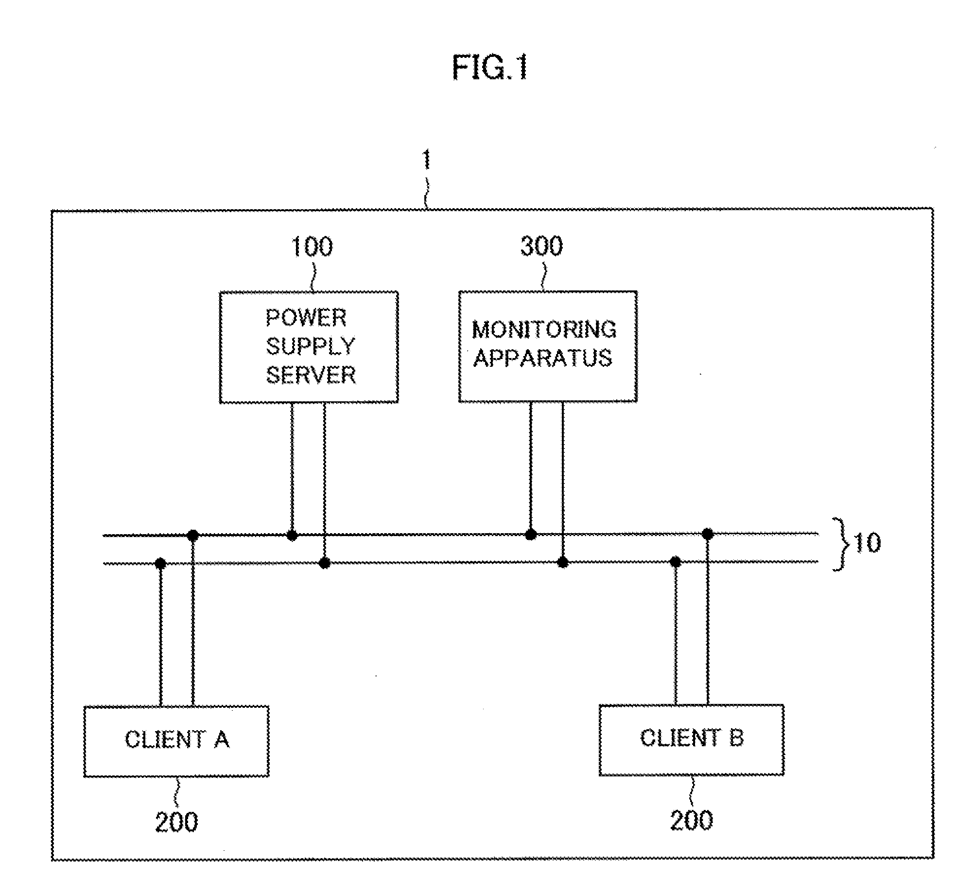
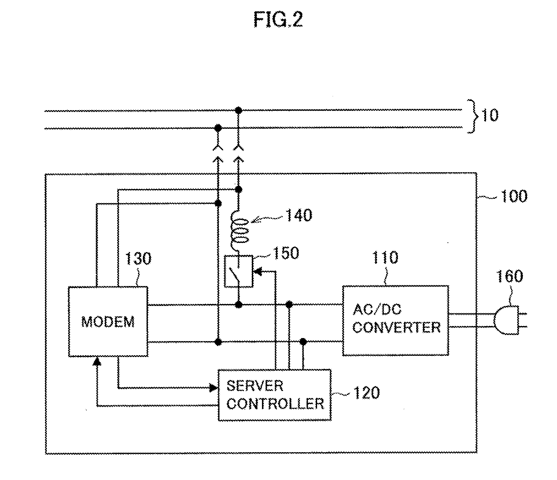
[0039]The configuration of a power supplying system 1 according to a first embodiment of the present invention is described hereinafter with reference to FIGS. 1 to 4. FIG. 1 is an explanatory view showing the schematic configuration of the power supplying system 1 according to the embodiment. FIG. 2 is an explanatory view showing the configuration of a power supply server 100 according to the embodiment. FIG. 3 is an explanatory view showing the configuration of a client according to the embodiment. FIG. 4 is an explanatory view showing the configuration of a monitoring apparatus according to the embodiment.

[0040]In the power supplying system 1 according to the embodiment, a power supply server 100, a client 200 and a monitoring apparatus 300 are connected to one bus line 10 as shown in FIG. 1. Although one power supply server 100, two clients 200 and one monitoring apparatus 300 are connected through the bus line 10 in this embodiment, one or two or more power supply servers 100, ...

second embodiment

[0077]A power supplying system according to a second embodiment of the present invention is described hereinafter with reference to FIGS. 8 to 10. In the power supplying system of this embodiment, the power supply server 100, the client 200 and the monitoring apparatus 300 are connected through the bus line 10 as shown in FIG. 1, just like the first embodiment. However, the monitoring apparatus 300 of this embodiment is capable of exchanging an information signal with the power supply server 100 and the client 200, which is different from the first embodiment.

[0078]The display processing of an information signal by the monitoring apparatus 300, which is different from that of the first embodiment, is described hereinbelow. FIG. 8 is a flowchart showing an example of the server power profile display processing which is performed between the monitoring apparatus 300 and the power supply server 100 according to this embodiment. FIG. 9 is an explanatory view showing an example of the co...

third embodiment

[0096]A power supplying system according to a third embodiment of the present invention is described hereinafter with reference to FIG. 13. FIG. 13 is an explanatory view showing the configuration of a monitoring apparatus 400 according to the embodiment. In the power supplying system according the embodiment, the power supply server 100, the client 200 and the monitoring apparatus 400 are connected through the bus line 10 as shown in FIG. 1, just like the first embodiment. The power supply server 100, the client 200 and the monitoring apparatus 400 according to this embodiment have an interface portion which can be connected without through the bus line 10. The power supplying system according to the embodiment is described hereinafter, mainly about a difference from the first embodiment. The same configuration and function as those of the first embodiment are not described in detail herein.

[0097]The configuration of the monitoring apparatus 400 according to the embodiment is descr...


PUM


Abstract

A power supplying system is configured so that a power supply server for supplying power and a client for receiving power are connected through a bus line on which an information signal representing information and power exist superimposed on one another, and the information signal is exchanged between the power supply server and the client. To the bus line of the power supplying system, a monitoring apparatus to monitor at least one of the information signal and power information related to power is connected. The monitoring apparatus includes a receiving portion to detect an information signal existing on the bus line, and a display control portion to display at least one of the information signal and the power information exchanged between the power supply server and the client.

Description

CROSS REFERENCES TO RELATED APPLICATIONS[0001]The present invention contains subject matter related to Japanese Patent Application JP 2007-283380 filed in the Japan Patent Office on Oct. 31, 2007, the entire contents of which being incorporated herein by reference.BACKGROUND OF THE INVENTION[0002]1. Field of the Invention[0003]The present invention relates to a power supplying system in which a power supply server to supply power and a client to receive power are connected through a bus line, a monitoring apparatus, a monitoring method and a computer program.[0004]2. Description of the Related Art[0005]There are used many battery-operated devices such as a personal computer. A large majority of battery-operated devices uses an AC adapter for battery charging and device operation. Although a direct current (DC) is usually used as input to a battery-operated device, because its voltage and current capacity is different, an AC adapter is basically dedicated to each device. Further, an ...

Claims


Application Information

Patent Timeline
IPC IPC(8): G06F11/32G06F1/00
CPCH04L12/40045H04L12/10
Inventor TAJIMA, SHIGERUNISHIDA, YOSHIFUMI
Owner SONY CORP
Why Eureka
Try Eureka