
Preassembled tower section of a wind power plant

a technology for wind power plants and tower sections, which is applied in the direction of final product manufacturing, building repair, electric generator control, etc., can solve the problems of cumbersome and expensive transportation of bulky components of wind power plants from fabrication sites to installation sites

Active Publication Date: 2009-08-27
GENERAL ELECTRIC CO
View PDF8 Cites 15 Cited by
  • Summary
  • Abstract
  • Description
  • Claims
  • Application Information

AI Technical Summary

Benefits of technology

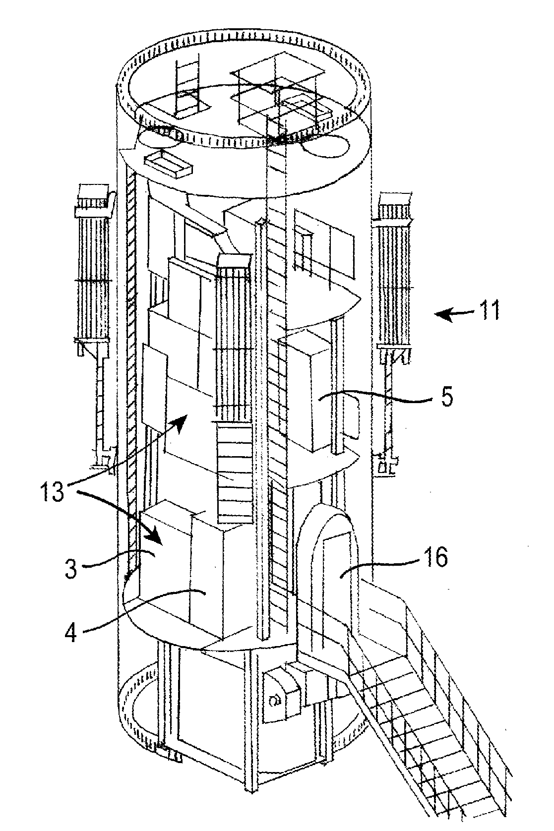
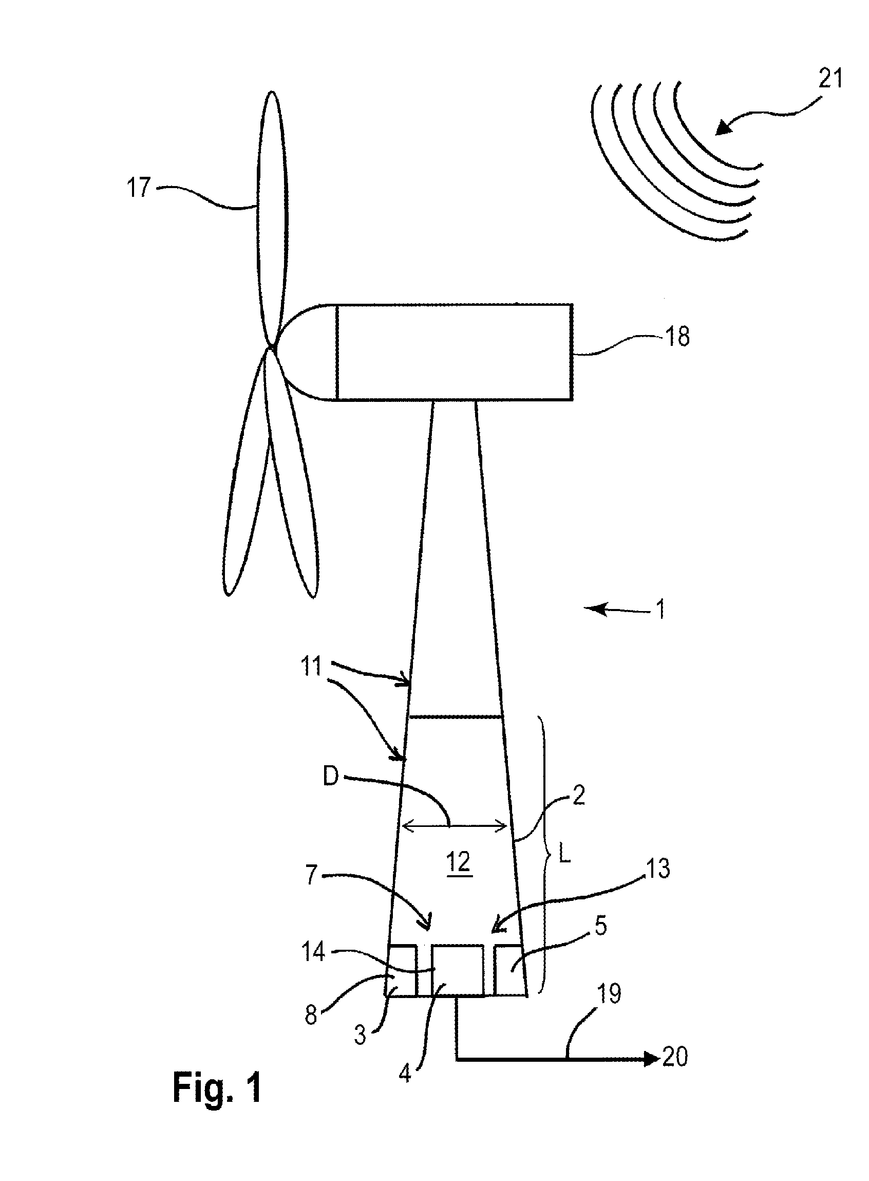
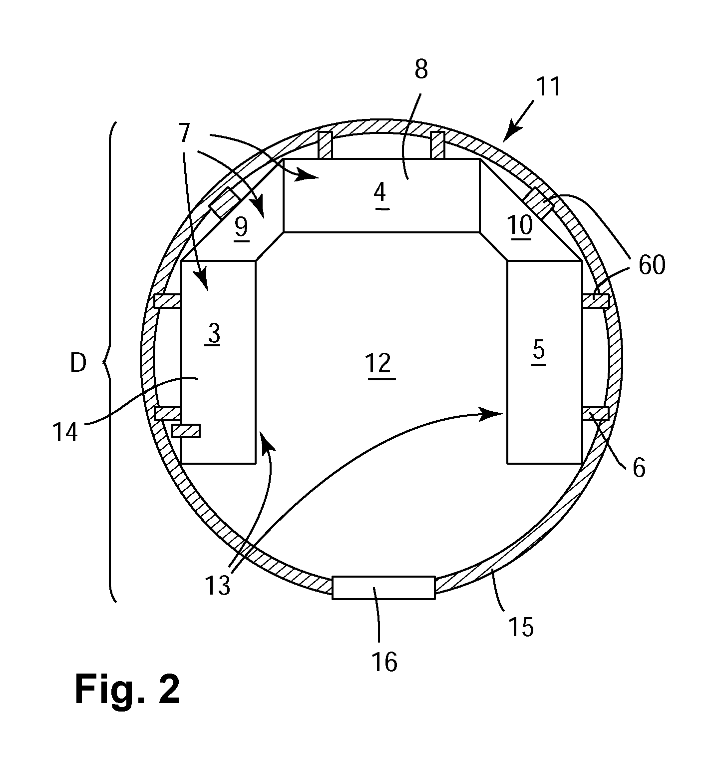
[0012]By preassembling at least one of the electronic subsystems onto the tower section and transporting the tower section together with the electronic subsystem, transportation of the wind power plant to the installation site is significantly reduced.
[0014]Furthermore, the level of the modular design of the wind power plant is increased and the efforts for installing the wind power plant at the installation site is reduced. In effect the time when highly trained personal needs to supervise the installation is further reduced.
[0016]Advantageously more than half of the electronic subsystems are preassembled onto the tower section at the preassembly site. The more electronic subsystems are preassembled onto the tower section at the preassembly site, the easier it is to install the wind power plant at the installation site.
[0018]In an embodiment, at the preassembly side at least two electronic subsystems are interconnected by wiring. Taking this measure, the level of preassembly is further increased. This saves time for installation of the wind power plant. Further, certain testing algorithms to be performed at the installation site become superfluous or become at least more simple.

Problems solved by technology

Due to the increasing size of the respective units, transporting the bulky components of a wind power plant from a fabrication site to an installation site is cumbersome and expensive.

Method used


Image

  • Preassembled tower section of a wind power plant
  • Preassembled tower section of a wind power plant
  • Preassembled tower section of a wind power plant

Examples


Embodiment Construction

[0006]Reference will now be made in detail to the various embodiments of the invention, one or more examples of which are illustrated in the figures. Each example is provided by way of explanation of the invention, and is not meant as a limitation of the invention. For example, features illustrated or described as part of one embodiment can be used on or in conjunction with other embodiments to yield yet a further embodiment. It is intended that the present invention includes such modifications and variations.

[0007]Due to the large size and heavy weight of modern wind power plants that have been increasing in size, volume and weight over the past years, the costs for transportation have steadily increased and form a substantial portion of the overall costs of a wind power plant. Furthermore, as the various system components are commonly assembled at an installation site of the wind power plant, highly trained personal is required to assist the assembly of the wind power plant at the...


PUM


Abstract

The present invention relates to a preassembled tower section of a wind power plant and a method of transporting a tower section of a wind power plant, the method comprising the steps providing the tower section at a preassembly site, preassembling at least one electronic subsystem of the wind power plant onto the tower section, transporting the preassembled tower section from the preassembly site to an installation site. In effect transport thereof is considerably simplified and a higher degree of modular design and preassembly is achieved.

Description

BACKGROUND OF THE INVENTION[0001]The present invention relates to wind turbines and wind power plants. Particularly, the invention relates to a method of transporting a tower section of a wind power plant and to a tower section of a wind power plant.[0002]Wind power plants and wind turbines increase in size and dimension. Usually, system components such as power electronic boards, switch boards, electronic cabinets or transformers as well as other bulky elements of a wind power plant such as a tower section of the wind power plant to which a nacelle is attached at its top, as well as other components (such as a wind turbine drive train or the generator) are transported as individual units from a fabrication side to an installation side of the wind power plant where the units are assembled. Due to the increasing size of the respective units, transporting the bulky components of a wind power plant from a fabrication site to an installation site is cumbersome and expensive.SUMMARY OF T...

Claims


Application Information

Patent Timeline
Patent Type & Authority Applications(United States)
IPC IPC(8): E04H12/00
CPCF03D1/001F03D1/005Y02E10/728F05B2230/60F03D11/04F03D13/20F03D13/10F03D13/40F03D80/82Y02E10/72Y02P70/50F03D13/205
Inventor SCHOLTE-WASSINK, HARTMUT
Owner GENERAL ELECTRIC CO
Learn More