Flue gas purification device and circulating fluidized bed boiler equipped with the device

A circulating fluidized bed and flue gas purification technology, which is applied to fluidized bed combustion equipment, fuel burning in a molten state, and gas treatment, etc., can solve the problems of catalyst loss, failure to achieve denitration rate, and high investment and operating costs. Achieve the effect of reducing the difficulty of processing and installation, reducing the power of the blower, and reducing the amount of steel

Active Publication Date: 2019-05-28
ENVIRONMENTAL PROTECTION EQUIP CO LTD SHANDONG GIANT ASIA +1
View PDF9 Cites 0 Cited by
  • Summary
  • Abstract
  • Description
  • Claims
  • Application Information

AI Technical Summary

Problems solved by technology

[0003] However, during the use of the circulating fluidized bed, the flue gas generated contains more nitrogen oxides and sulfides, which are one of the main harmful substances that pollute the air.
In order to deal with harmful substances such as nitrogen oxides, technologies such as SCR and SNCR are mainly used at home and abroad to treat nitrogen oxides. The above two technologies use ammonia water as a reducing agent to treat nitrogen oxides in the process of processing nitrogen oxides. reaction, SCR mainly uses TiO 2 as a carrier to contain V 2 o 5 The composition of the catalyst is used as a catalyst to speed up the reaction, and the denitrification rate is high, but it is easy to cause the loss of the catalyst, the equipment occupies a large space, and the investment and operation costs are high. The catalyst is easy to cause secondary heavy metal pollution when the catalyst is operated carelessly; although the use of SNCR technology reduces The use of catalysts reduces the cost of equipment operation investment, but the reaction is not complete, the denitrification efficiency is low, the ideal denitrification rate cannot be achieved, and the flue gas purification effect is not thorough
In order to deal with the sulfide contained in the flue gas, the commonly used technology is the limestone method or the double alkali method for desulfurization, but the above-mentioned sulfide treatment method and the nitrogen oxide treatment method are carried out separately in practical applications, and the treatment equipment Many, complex process, high investment cost

Method used


Image

  • Flue gas purification device and circulating fluidized bed boiler equipped with the device
  • Flue gas purification device and circulating fluidized bed boiler equipped with the device
  • Flue gas purification device and circulating fluidized bed boiler equipped with the device

Examples


Embodiment 1

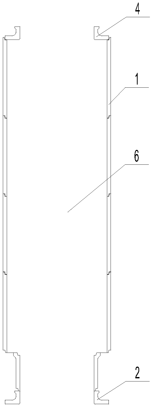
[0025] Embodiment 1: A flue gas purification device, including several pipelines 6 arranged side by side or alternately, the pipeline 6 includes a middle section 1, an inlet section 2, and an outlet section 4, and the inner diameters of the inlet section 2 and the outlet section 4 are smaller than the middle section 1 enclosed inner diameter.

Embodiment 2

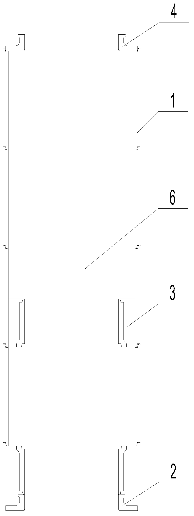
[0026] Embodiment 2: A flue gas purification device, including several pipes 6 arranged side by side or alternately, the pipe 6 includes a middle section 1, an inlet section 2, and an outlet section 4, and the inner diameters of the inlet section 2 and the outlet section 4 are smaller than the middle section Inner diameter enclosed by segment 1. An inner diameter reducing section 3 is provided on the inner wall of the middle section 1 , and the inner diameter enclosed by the inner diameter reducing section 3 is smaller than or equal to the inner diameters of the inlet section 2 and the outlet section 4 . There is one inner diameter narrowing section 3 , which is located in the middle of the middle section 1 near the inlet section 2 . The cross sections of the inlet section 2, the pipe 6, the inner diameter reducing section 3 and the outlet section 4 are circular. The pipeline 6 is a split assembly structure.

Embodiment 3

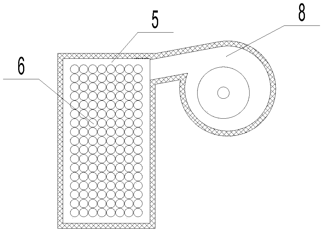
[0027] Embodiment 3: A circulating fluidized bed boiler equipped with a flue gas purification device, including a furnace 7, a separator 8, a feeding device and a heat exchanger, the furnace 7 is connected to the separator 8, and the separator 8 is installed below the Return device, the return device is connected with the furnace 7, the heat exchanger is located at one side of the separator 8 and connected with the separator 8, wherein the air inlet 9 of the furnace 7 is provided with a wind cap 10, and the top of the wind cap 10 is installed with A flue gas purification device, the flue gas purification device includes a number of pipes 6 arranged side by side or alternately, the pipe 6 includes a middle section 1, an inlet section 2, and an outlet section 4, and the inner diameters of the inlet section 2 and the outlet section 4 are smaller than that of the middle section 1 enclosed inner diameter; the refractory material 5 is poured between the adjacent pipes 6 and between t...


PUM


Abstract

The invention discloses a flue gas purifying device and a circulating fluidized bed boiler with the device, and belongs to the technical field of boiler environment friendliness. The flue gas purifying device and the boiler are used for treatment of nitrogen oxides and sulfides. The flue gas purifying device comprises a plurality of pipelines which are arranged in parallel or alternatively, each pipeline comprises a middle segment, an inlet segment and an outlet segment, and the inner diameter of each inlet segment and each outlet segment is smaller than the inner diameter of a portion defined by the corresponding middle segment; and in view of the technical scheme, simultaneous and efficient treatment of the nitrogen oxides and the sulfides in flue gas through the enhanced SNCR technology can be achieved, equipment investment and operating maintenance cost can be reduced, and the pollution of secondary heavy metal pollution is completely eradicated.

Description

technical field [0001] The invention belongs to the technical field of boiler environmental protection, and in particular relates to a flue gas purification device and a circulating fluidized bed boiler equipped with the device. Background technique [0002] The circulating fluidized bed can make small particles of coal and air boil in the furnace, so that the high-speed airflow can fully contact and burn the dense suspended coal particles carried by it. Due to its high reliability, high stability, high availability, high environmental protection characteristics and wide fuel adaptability, circulating fluidized bed has attracted more and more attention, and is suitable for my country's national conditions and development trends. [0003] However, during the use of the circulating fluidized bed, the flue gas generated contains more nitrogen oxides and sulfides, which are one of the main harmful substances that pollute the air. In order to deal with harmful substances such as...

Claims


Application Information

Patent Timeline
Patent Type & Authority Patents(China)
IPC IPC(8): F23C10/20B01D53/48B01D53/56B01D53/78
CPCB01D53/48B01D53/56B01D53/78B01D2251/2062B01D2251/2067B01D2258/0283B01D2259/124F23C10/20
Inventor 张亚玉
Owner ENVIRONMENTAL PROTECTION EQUIP CO LTD SHANDONG GIANT ASIA
Why Eureka
Try Eureka