
Fatigue life estimating method for spot welded structure

a spot welded and life-estimating technology, which is applied in the direction of material strength using steady bending force, using mechanical means, instruments, etc., can solve the problems of reducing the physical strength of the vehicle, not easy to calculate the nominal structural, and the preparation of the database db>2/b> is also labor-intensive. , to achieve the effect of easy and quick estimation of the life of the spot welded structur

Inactive Publication Date: 2009-08-27
NIHON UNIVERSITY
View PDF5 Cites 11 Cited by
  • Summary
  • Abstract
  • Description
  • Claims
  • Application Information

AI Technical Summary

Benefits of technology

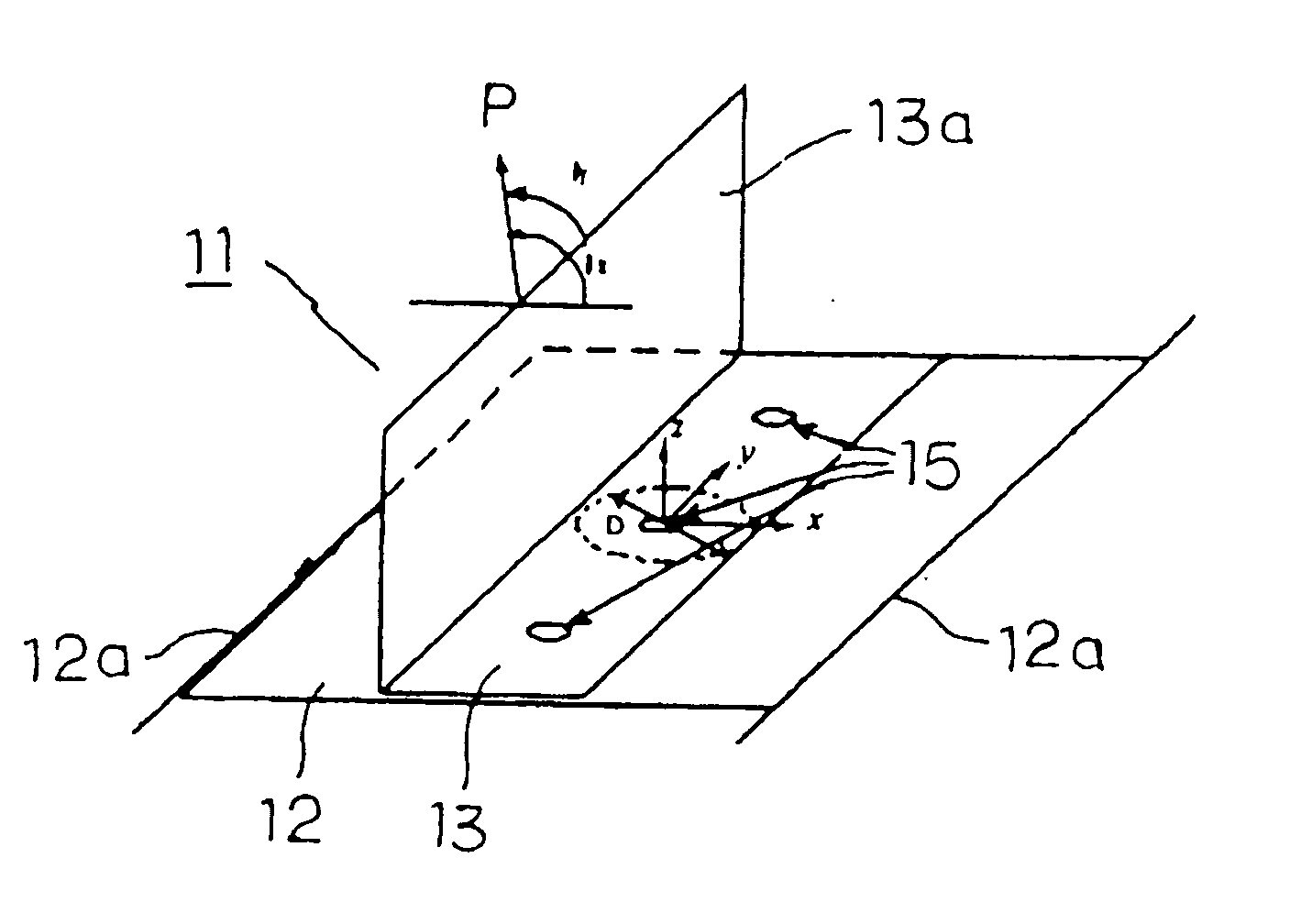
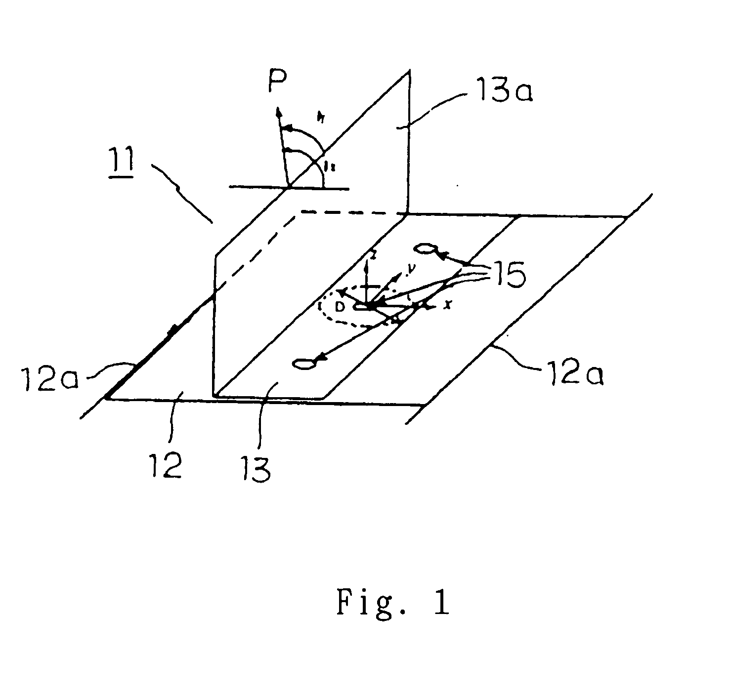
[0025]According to the feature of claim 1, a disk having a diameter of D and including the nugget of interest at the center is separated from the spot welded structure and stained at the outer edge when loaded at the nugget with partial forces of peel load, bending moment, shear load, and torsional moment for calculating the nominal structural stress. This allows no database of the D diameter to be needed and the troublesome task for determining an optimum of the D diameter to be eliminated. As the result, the fatigue life of the spot welded structure can be estimated easily and readily.

Problems solved by technology

In particular, the loads may be intensified at the welding contacts thus declining the physical strength of the vehicle.
It is hence not easy for calculating the nominal structural stress σns on the disk of spot welded structure to determine an optimum of the diameter D of the disk.
It is true that the preparation of the database D2 is also a labor intensive task.
Therefore, it will be a drawback for calculation of the equations to determine the diameter D of the disk 2 to an optimum.
It will hence be difficult to calculate the stress at higher accuracy through comparison with that of the infinite plate.
It is thus understood that Equation 3 is unfavorable for determining the stress for the case.

Method used


Image

  • Fatigue life estimating method for spot welded structure
  • Fatigue life estimating method for spot welded structure
  • Fatigue life estimating method for spot welded structure

Examples


example 1

[0109]Prior to its application to the spot welded structure, the solution from the method of this embodiment is examined through comparing with the exact solution from the distribution of deflection, as shown in FIG. 5, where the disk shown in FIG. 3 is perfectly arrested at the circumference for no deflection and loaded with the peel load and the bending moment separately.

[0110]As apparent, the solution from the method is similar to the exact solution as based on the circumferential condition (the right side of Equation 6) determined by the deflection and the tilting at the intermediate of the disk (the peel load: r=3.82 (d / 2), the bending moment: r=3.82 (d / 2)).

[0111]FIGS. 6a and 6b illustrate comparison between the distribution of the stress σr, calculated by the method of the present invention, along the x direction extending across the center of the nugget 15 and its counterpart from the FEM solid solution. LP# θx and θy represent the loads exerted in the θx and θy directions re...

example 2

[0113]While the nominal structural stress is calculated responsive to the peel load or the bending moment in Example 1, Example 2 is a case that the shear load is dominant as the partial load. It is typically assumed that the shear load is exerted on a test piece composed of three equal thickness strips joined together at one contact by spot welding (FIG. 8).

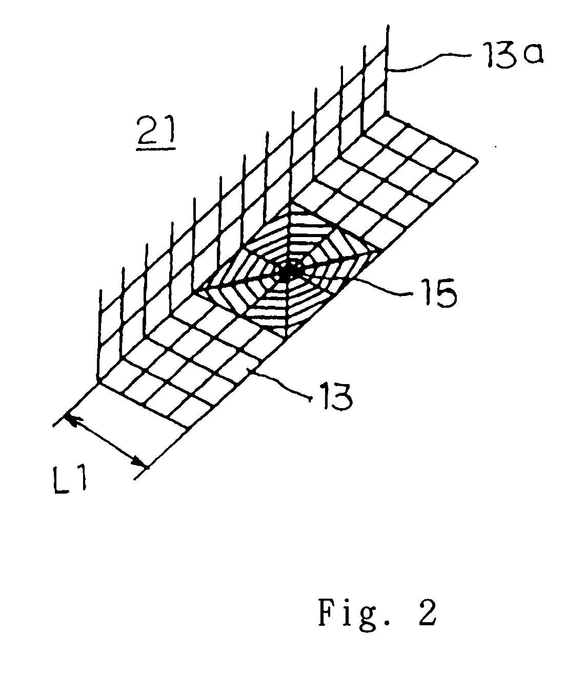
[0114]Firstly, the finite element method shell analyzing process is carried out for acquiring the node deflection used as the boundary condition. FIG. 9 illustrates an FEM shell analyzing model composed of three spot welded strips. As the model is expressed by a grating pattern of small square segments, its center square portion about the nugget is designated having each side arranged equal to the lap length, which is divided radially by two at the nugget, by four at the other area than the nugget, and circumferentially by eight. The nugget includes bar elements arranged radially and extending along one side of the shell element...

example 3

[0121]Using a two, large and small, flat plates joined together by spot welding as shown in FIG. 27, the stress vertical to the loading direction is measured in response to a uniform tensile force a loaded at both sides. The procedure starts with preparing the analyzing model with shell elements as shown in FIG. 11 and calculating the distribution of the stress at the node points or vertices of an octagonal shape about the nugget. The resultant distribution is shown in FIG. 12. The distribution of the stress calculated by the method of the embodiment is favorably more similar to that of the FEM solid analyzing process than by the conventional method.


PUM


Abstract

A fatigue life estimating method for a spot welded structure is provided comprising the steps of providing a shell model of a spot welded structure for a finite element method analyzing process, calculating the nominal structural stress on a nugget as the center of the spot welded structure using a disk bending theory and a two-dimensional elastic theory of the elastodynamics with the partial loads exerted on the nugget and the deflection on the circumference of a circle, D in diameter, in which the nugget is located, which have been calculated by the finite element method analyzing process of the shell model, and estimating the fatigue life of the spot welded structure from the nominal structure stress.According to the method, the fatigue life of the spot welded structure can be estimated easily, readily, and accurately.

Description

FIELD OF THE INVENTION[0001]The present invention relates to a fatigue life estimating method for a spot welded structure and particularly to a fatigue life estimating method for estimating the fatigue life of a spot welded structure from a nominal structural stress which has been calculated from the partial load at a nugget in the spot welded structure while producing a finite element method analyzing shell model of the spot welded structure.BACKGROUND OF THE INVENTION[0002]In the field of automobile research and development, a variety of estimation methods using a computer-aided CAE technology have been proposed progressively for minimizing the weight of vehicles, the length of time for the development, and the number of prototype vehicles. Among of them is estimation of the physical strength of a vehicle which has also been vigorously studied.[0003]The body of a vehicle is generally fabricated by sheet metals. The sheet metals are commonly joined together by spot welding. During ...

Claims


Application Information

Patent Timeline
IPC IPC(8): G01N3/24G01N3/00
CPCG01N3/00G01N2203/0073G01N2203/0214G06F2217/76G06F17/5018G06F2217/42G01N2203/0216G06F2113/24G06F2119/04G06F30/23G01N19/00
Inventor TOMIOKA, NOBORU
Owner NIHON UNIVERSITY
Learn More