Surface defect judging method

a surface defect and judging method technology, applied in the field of surface defect judging method, can solve the problems of long time required to start up the surface defect detection apparatus, difficult to quickly adapt to such a change, and difficult to solve the problem of complicated task

Inactive Publication Date: 2005-08-11
JFE STEEL CORP
View PDF0 Cites 15 Cited by
  • Summary
  • Abstract
  • Description
  • Claims
  • Application Information

AI Technical Summary

Benefits of technology

[0018] In the fifth aspect of the present invention, the surface defect classification method according to one of the first to fourth aspect is implemented in the decision tree, thereby making it possible to discriminate a plurality of defect types and / or defect levels.

Problems solved by technology

Thus, a troublesome and complicated task is needed to finally establish a decision algorithm, and it takes a long time to start up a surface defect detection apparatus.
If the material or the production method of the product to be tested is changed, the troublesome and long task described above must be performed again from the beginning to establish the decision algorithm, and thus it is difficult to quickly adapt to such a change.
However, in practice, use of a large number of features makes it difficult to perform analysis, and thus there is a limit on improvement in accuracy of defect classification for the defect type or the defect level.
However, the technique using the neural network needs to learn a huge number of data in an inefficient manner and thus the learning needs a long time.
Besides, because the decision algorithm is produced in a black box, it is impossible to modify the decision algorithm hidden in the black box even if decision is not correct for a particular surface defect.

Method used


Image

  • Surface defect judging method
  • Surface defect judging method
  • Surface defect judging method

Examples


example 1

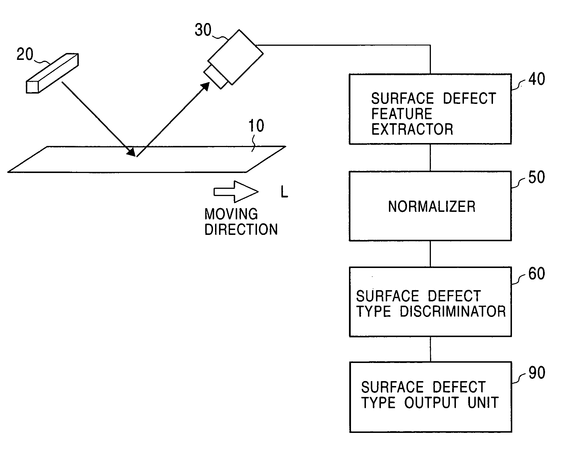
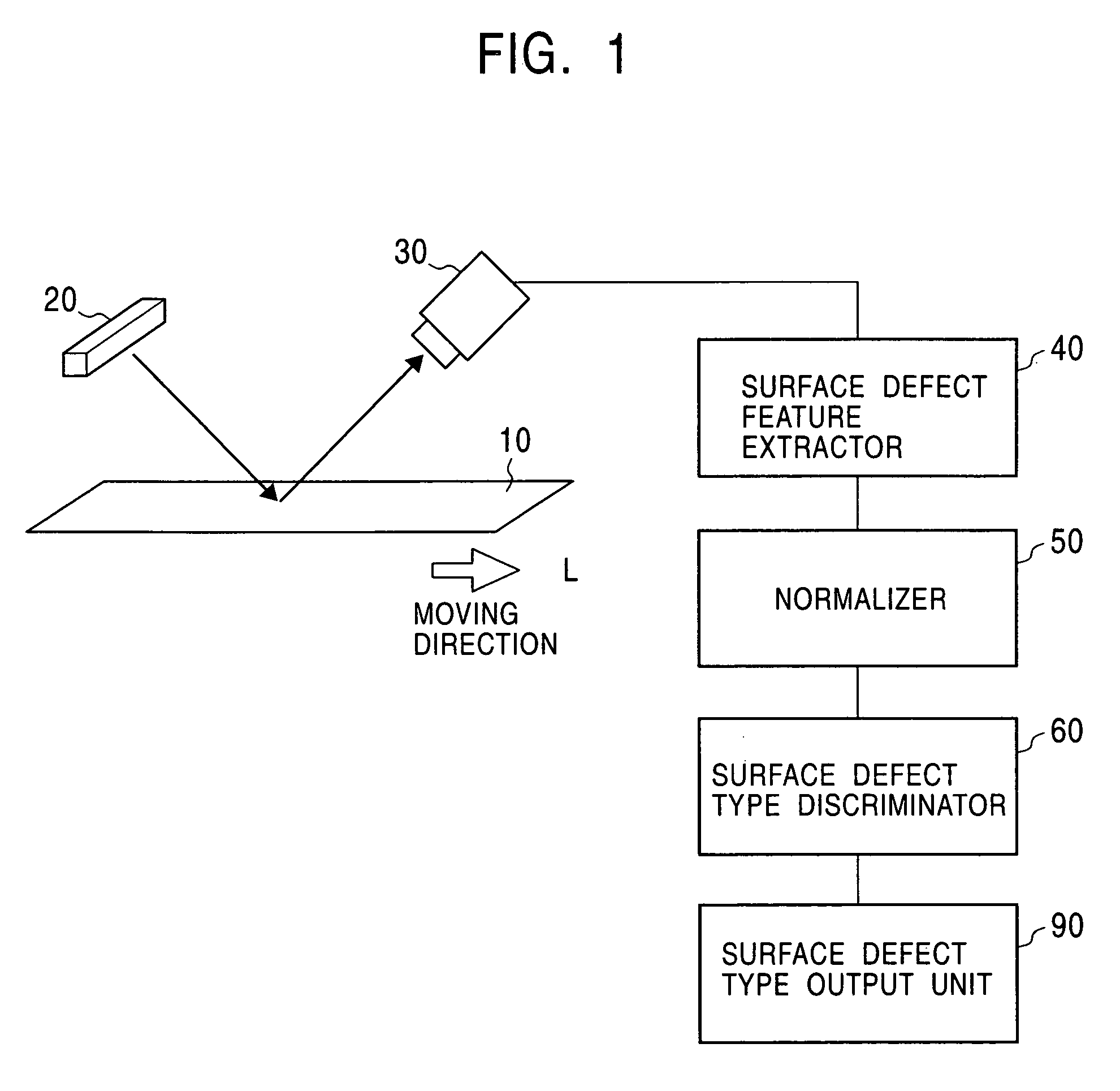
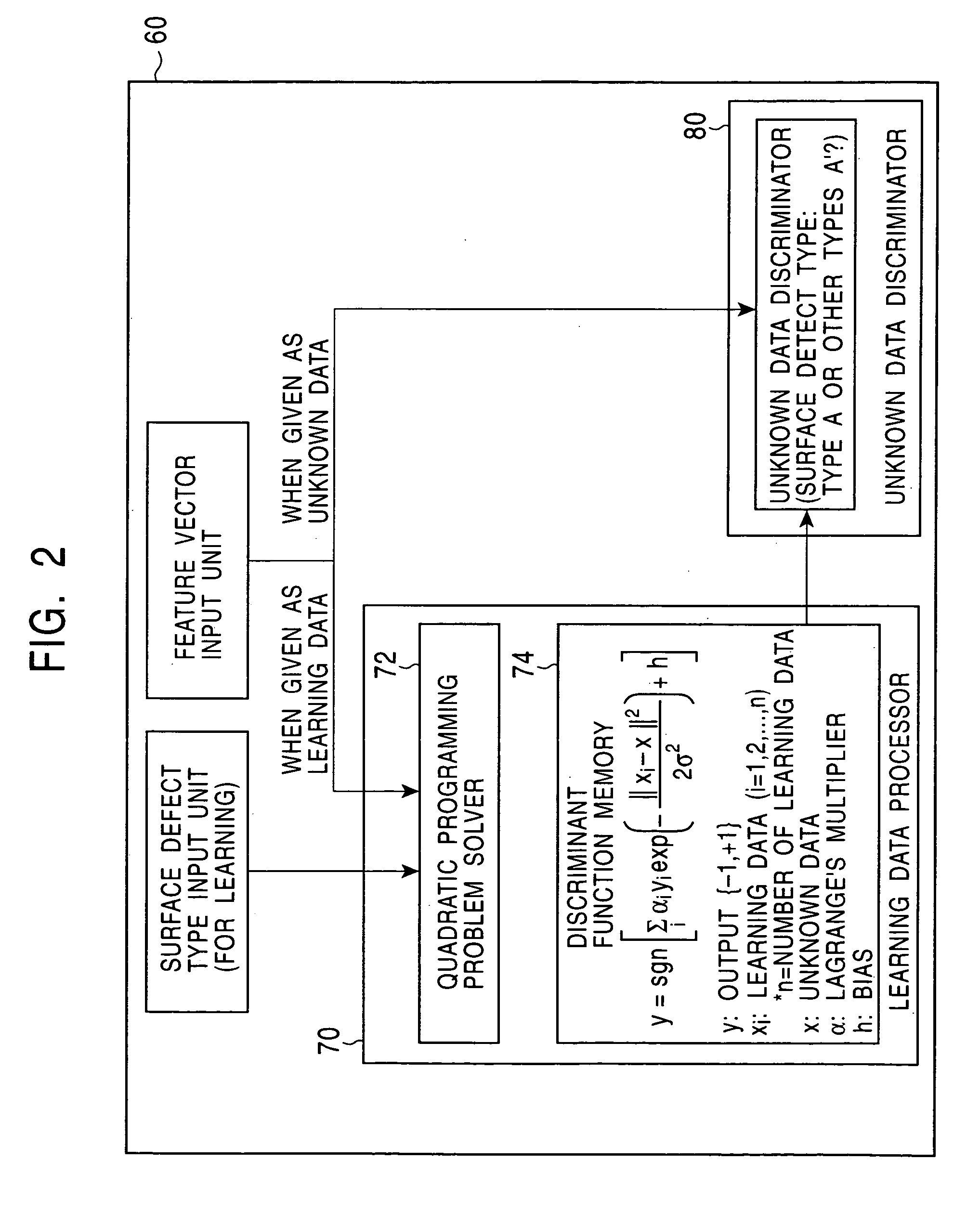
[0043] The method of learning performed by the learning data processor 70 of the surface defect type discriminator 60 is described in detail below for a case in which the surface defect type A is discriminated from the other surface defect types A′. A feature vector xi of learning data represented as a point in the feature space is mapped by an assumed mapping function Φ as xi→Φ(xi), wherein the mapping function satisfies the following condition.

Φ(xi)·Φ(xj)=K(xi·xj)  (3)

[0044] That is, when feature vectors xi and xj in the feature space are mapped by the mapping function Φ to the space Φ, the inner product Φ(xi)·Φ(xj) in the space Φ is equal to the function of the inner product xi·xj in the feature space.

[0045] Herein, i and j respectively denote learning data numbers, that is, [0046] i, j=1, 2, . . . , n (n is the number of learning data)

[0047] It is assumed that, in the mapping, the distance relationship in the feature space is preserved, and it is also assumed that, in the ma...

example 2

[0066] In practice, the distributions of the sets in the feature space are probabilistic, and data can include wrong data (that is incorrectly selected by a human inspector). Therefore, all learning data are not necessarily correct.

[0067] In this second example, in view of the above, the constraint in terms of complete linear separability imposed in the first example is relaxed. More specifically, the feature space is allowed to include a point that can cause an incorrect classification, and a penalty term is added to the objective function used in the first example, as described below.

[0068] In the present example, to allow incorrect classification, variable ξ is introduced into the constraint, and a penalty parameter C imposed on incorrect classification is introduced. Thus, equation (9) is rewritten as follows. objective⁢ ⁢function⁢:⁢ ⁢w22+C⁢ ⁢∑i⁢ξi→maximizedconstraint⁢:⁢ ⁢yi·[w·Φ⁡(xi)+h]≥1-ξi(18)

[0069] If equation (18) is converted into the form of a dual problem by introduci...

example 3

[0073] In the second example described above, parameters are set such that the accuracy of defect classification for the surface defect type A (the probability that a defect determined to be of defect type A by a human inspector is correctly determined to be of defect type A by the surface defect detection apparatus) is substantially equal to the accuracy of defect classification for the surface defect type A′ other than the surface defect type A (the probability that a defect determined to be of defect type A′ by a human inspector is correctly determined to be of defect type A′ by the surface defect detection apparatus). In some applications, a particular type of surface defect can cause a very serious problem, and thus it is necessary to correctly detect such a type of surface defects without missing them. In this case, it is desirable to improve the accuracy of defect classification for that type of defects even if this results in a reduction in accuracy of defect classification ...


PUM

PropertyMeasurementUnit
surface defect classificationaaaaaaaaaa
distanceaaaaaaaaaa
surface defect classification methodaaaaaaaaaa

Abstract

A decision algorithm of discriminating a defect type and/or a defect level is automatically produced in a short time. The accuracy of defect classification in terms of a defect type or a defect level is improved. More specifically, feature values of surface defects acquired in the past are represented as points in a feature space, constraint is set that when the feature space is mapped into a space by an assumed mapping function, a discriminant plane can be defined in the mapped space such that mapped feature values are linearly separable perfectly with respect to the discriminant plane, an objective function is defined as the distance between the discriminant plane and a point located closest to the discriminant plane, an optimal discriminant plane is determined by solving a quadratic programming problem such that the objective function is maximized under the constraint, the determined discriminant plane is employed as a discriminant function, a feature value of a surface defect whose type is unknown is substituted into the discriminant function, and it is determined, from the resultant value of the discriminant function, whether the surface defect whose type is unknown is of the particular surface type.

Description

TECHNICAL FIELD [0001] The present invention relates to a method of discriminating the type or the level of a surface defect in a surface defect test. BACKGROUND ART [0002] In a typical known apparatus for detecting a surface defect of a product (hereinafter, referred to as a “material under test” (MUT)), as shown in FIG. 1, the surface of a moving MUT 10 is illuminated with light emitted by an external light source 20, light reflected from the surface of the MUT 10 is captured by a camera 30 and an image of the surface of the MUT 10 is taken, a feature value of a defect is extracted from the image, and the defect type or the defect level is determined from the extracted feature value. [0003] In such a surface defect detector, feature values associated with sizes such as a length, a width, and / or an area of a surface defect, feature values associated with shapes such as similarity to circle and / or aspect ratio, and feature values associated with image density such as an average imag...

Claims


Application Information

Patent Timeline
Patent Type & Authority Applications(United States)
IPC IPC(8): G01B11/30G01N21/892G06K9/62G06T1/00G06T7/00
CPCG01N21/892G06T7/0004G06K9/6234G01N2021/8854G06V10/7715G06F18/2132G06T7/00G01B11/30G06T1/00
Inventor HIRATA, TAKEHIDEASANO, KAZUYATOMURA, YASUO
Owner JFE STEEL CORP
Why Eureka
Try Eureka