
Stencil printing apparatus

Inactive Publication Date: 2009-08-27
RICOH KK
View PDF8 Cites 0 Cited by
  • Summary
  • Abstract
  • Description
  • Claims
  • Application Information

AI Technical Summary

Benefits of technology

[0007]It is an object of the present invention to provide a stencil printing apparatus which resolves the above problems and which is capable of reducing difficult cleaning work even when two-sided printing is performed continuously and of improving printing efficiency.

Problems solved by technology

Here, there is a problem that, because the lower side of the paper on which an image has been formed rubs against the upper face of the switching member while the re-fed paper passes through the switching member, smudging of the image is generated.
However, when two-sided printing is continuously performed, because ink and paper dust is gradually deposited like a clay on the upper face of the switching member and smudging is generated, there is a problem that the upper face of the switching member requires regular cleaning, which is difficult work, and that the printing efficiency drops.

Method used


Image

  • Stencil printing apparatus
  • Stencil printing apparatus
  • Stencil printing apparatus

Examples


Embodiment Construction

)

[0017]The present invention will be described in detail hereinbelow with reference to the drawings.

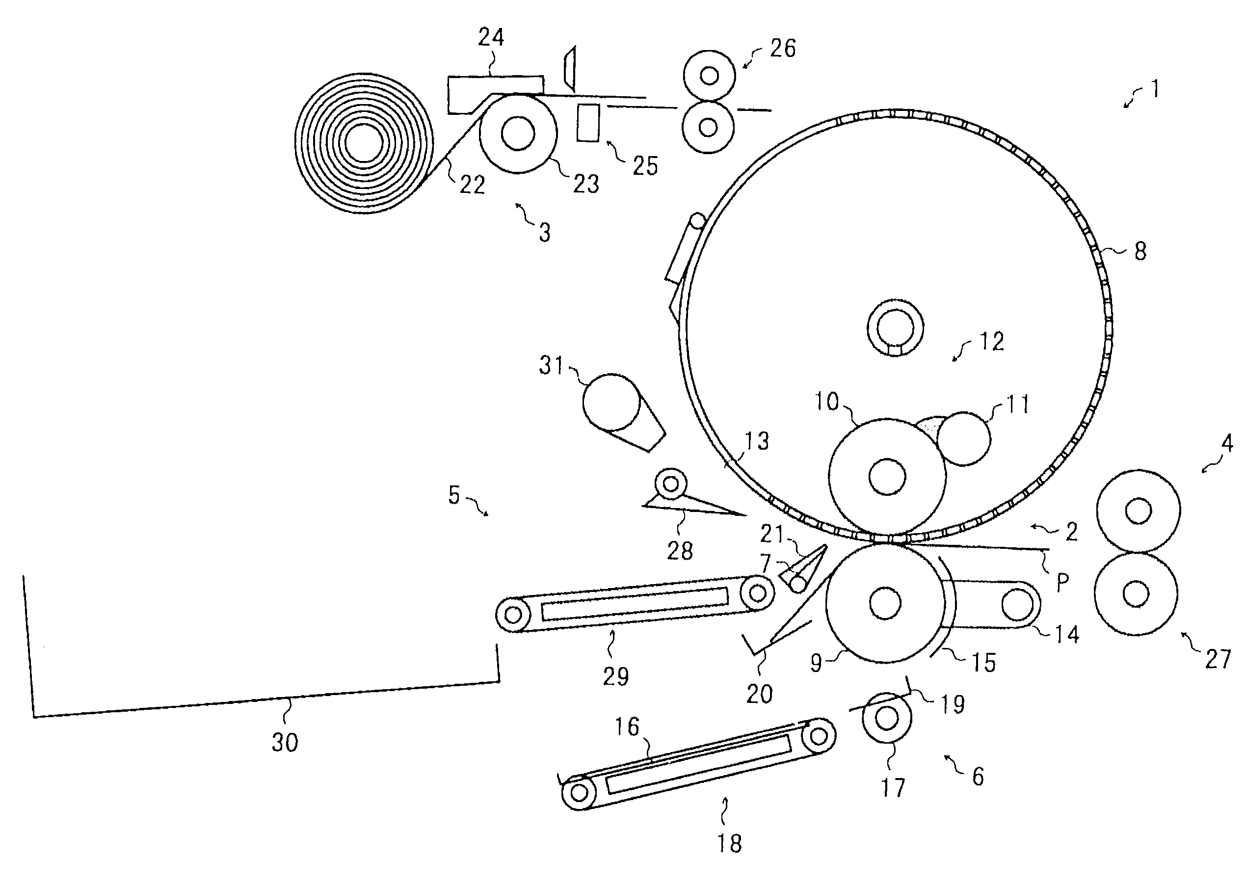
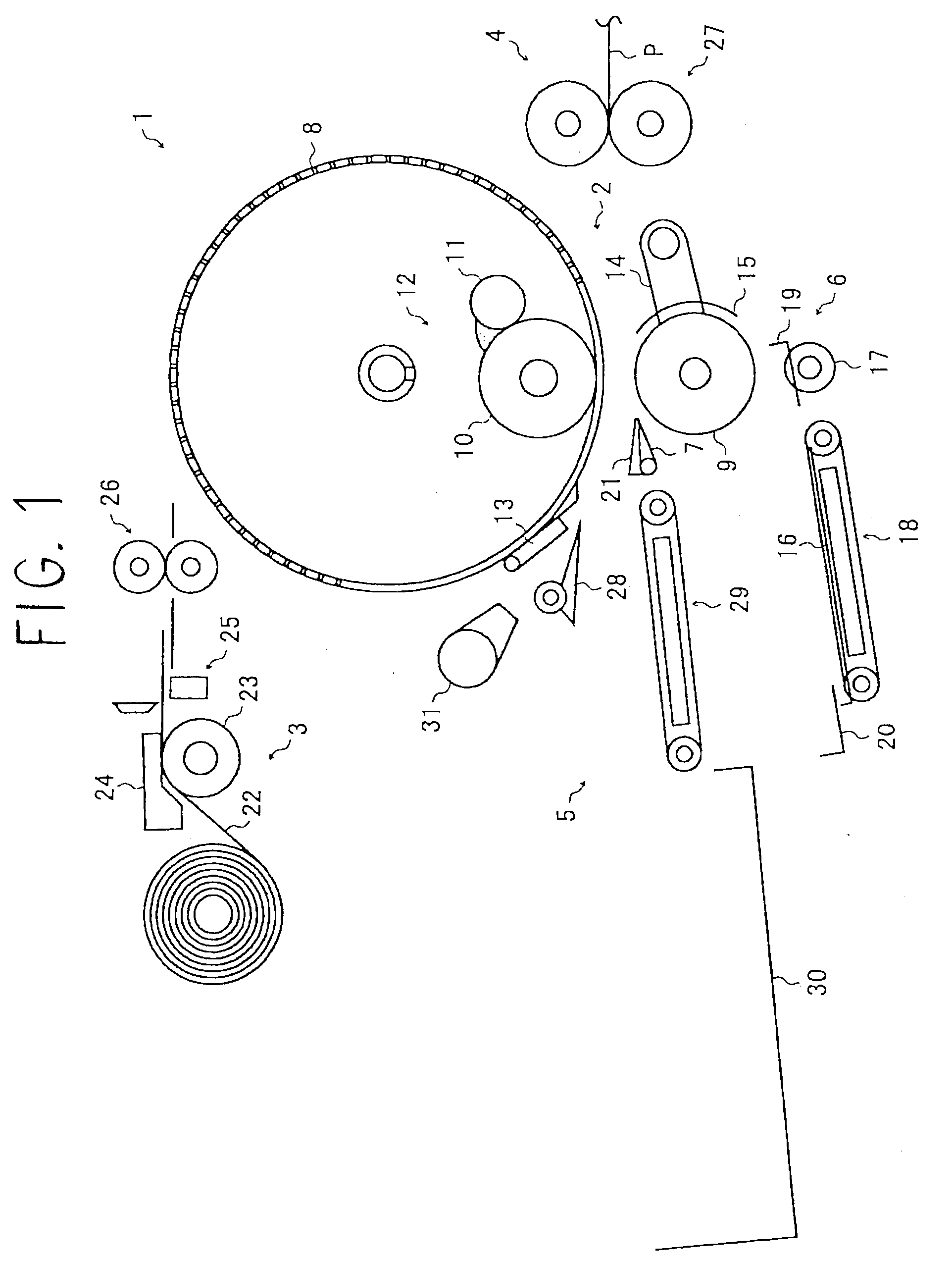
[0018]FIG. 1 shows the constitution of the stencil printing apparatus according to the present invention. The stencil printing apparatus has a constitution which is related to the two-sided printing apparatus disclosed in the above mentioned Japanese Patent Application Laid Open No. 2005-246730 and therefore a description of each of the parts of this stencil printing apparatus is omitted as far as possible.

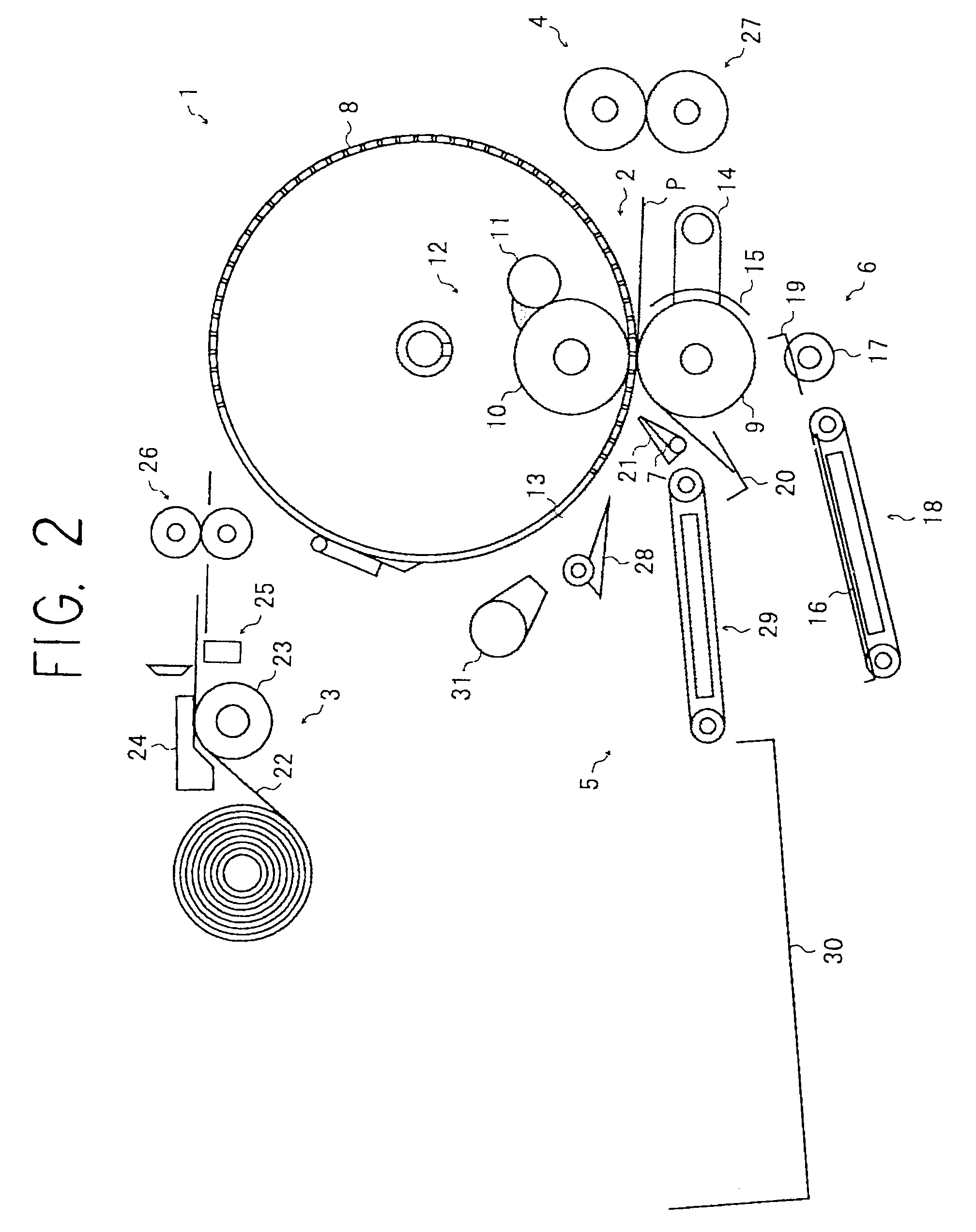
[0019]A stencil printing apparatus 1 in FIG. 1 comprises a printing portion 2, a plate-making portion 3, a paper-feeding portion 4, a plate discharge portion (not shown), a paper discharge portion 5, an image reading portion (not shown), paper re-feeding means 6, and a switching member 7, and the like.

[0020]The printing portion 2 which is disposed substantially in the middle of an apparatus main body (not shown) comprises a plate cylinder 8 and a press roller 9. The plate cylinder 8...


PUM


Abstract

A stencil printing apparatus which is capable of reducing difficult cleaning work even when two-sided printing is performed continuously and is capable of improving printing efficiency comprises a printing portion, a paper discharge portion, paper re-feeding means for re-feeding paper to the printing portion, and a displaceable switching member which selectively occupies a first position in which the paper that has passed through the printing portion is guided to the paper discharge portion and a second position in which the paper is guided to the paper re-feeding means. A reverse side printing step is performed in which the paper is re-fed to the printing portion by the paper re-feeding means after a surface printing step is performed, and the switching member comprises, on a face thereof opposite the paper when the switching member occupies the first position, a contact area reduction member for reducing the area of contact with the paper.

Description

BACKGROUND OF THE INVENTION[0001]1. Field of the Invention[0002]The present invention relates to a stencil printing apparatus which comprises paper re-feeding means and is capable of performing two-sided printing.[0003]2. Description of the Related Art[0004]Conventionally, digital heat-sensitive stencil printing is known as a simple printing method. This printing method makes a master plate by placing a thermal head comprising a plurality of microscopic heat-generating elements in contact with a master for whose fabrication a thermoplastic resin film is laminated on a porous substrate and by melt-perforating an image information-based perforation image into the thermoplastic resin film of the master by transporting the master by means of transporting means such as a platen roller while inputting power in pulses to the heat-generating elements, and subsequently obtains a print image on paper by wrapping the master, which has been perforated to render the master plate, around a porous...

Claims


Application Information

Patent Timeline
IPC IPC(8): B41L13/00
CPCB41L13/06
Inventor MIYAGI, TAKASHITAKAHASHI, MASANORIKOBAYASHI, KAZUYOSHI
Owner RICOH KK
Features
  • Generate Ideas
  • Intellectual Property
  • Life Sciences
  • Materials
  • Tech Scout
  • Unparalleled Data Quality
  • Higher Quality Content
  • 60% Fewer Hallucinations
Learn More