
Roll-Off Firebox Apparatus

a firebox and roll-off technology, applied in the field of waste disposal, can solve the problems of inconvenient and difficult installation in crowded or confined locations, neither of the portable solutions mentioned above is suitable for use in a congested urban environment, and is not available or readily provided

Active Publication Date: 2009-08-27
AIR BURNERS
View PDF13 Cites 6 Cited by
  • Summary
  • Abstract
  • Description
  • Claims
  • Application Information

AI Technical Summary

Benefits of technology

[0009]The firebox apparatus of the present invention further comprises an air curtain system for blowing air across the open top of the combustion chamber. A control room provided atop the front portion o

Problems solved by technology

Neither of the portable solutions mentioned above is suitable for use in a congested urban environment.
The apparatus of U.S. Pat. No. 4,756,258 requires a fire pit, something which is not available or readily provided in an urban setting where subterranean utility infrastructure is covered by pavement or concrete.
The apparatus of U.S. Pat. No. 5,415,113 must be lifted from and loaded onto a flatbed truck by a crane or lift, making it difficult and disruptive to install in crowded or confined locations.

Method used


Image

  • Roll-Off Firebox Apparatus
  • Roll-Off Firebox Apparatus
  • Roll-Off Firebox Apparatus

Examples


Embodiment Construction

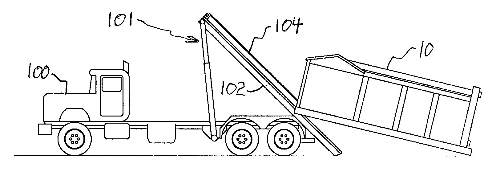
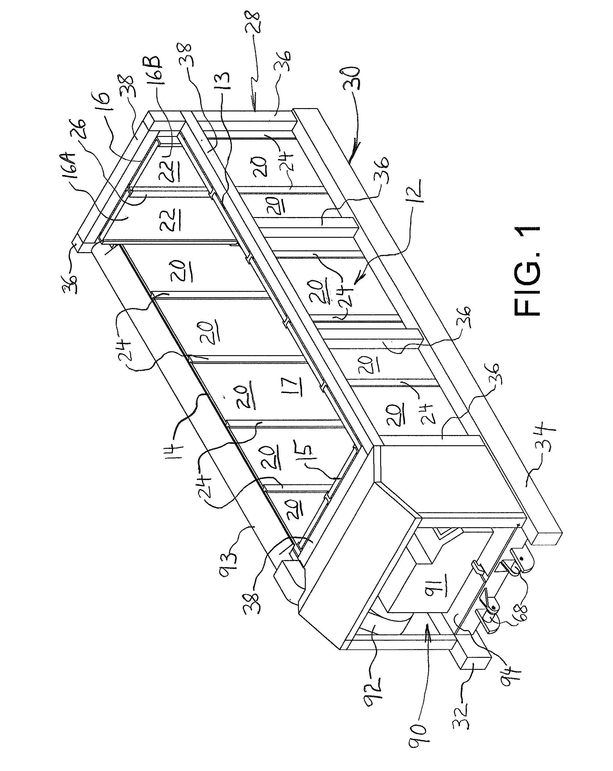
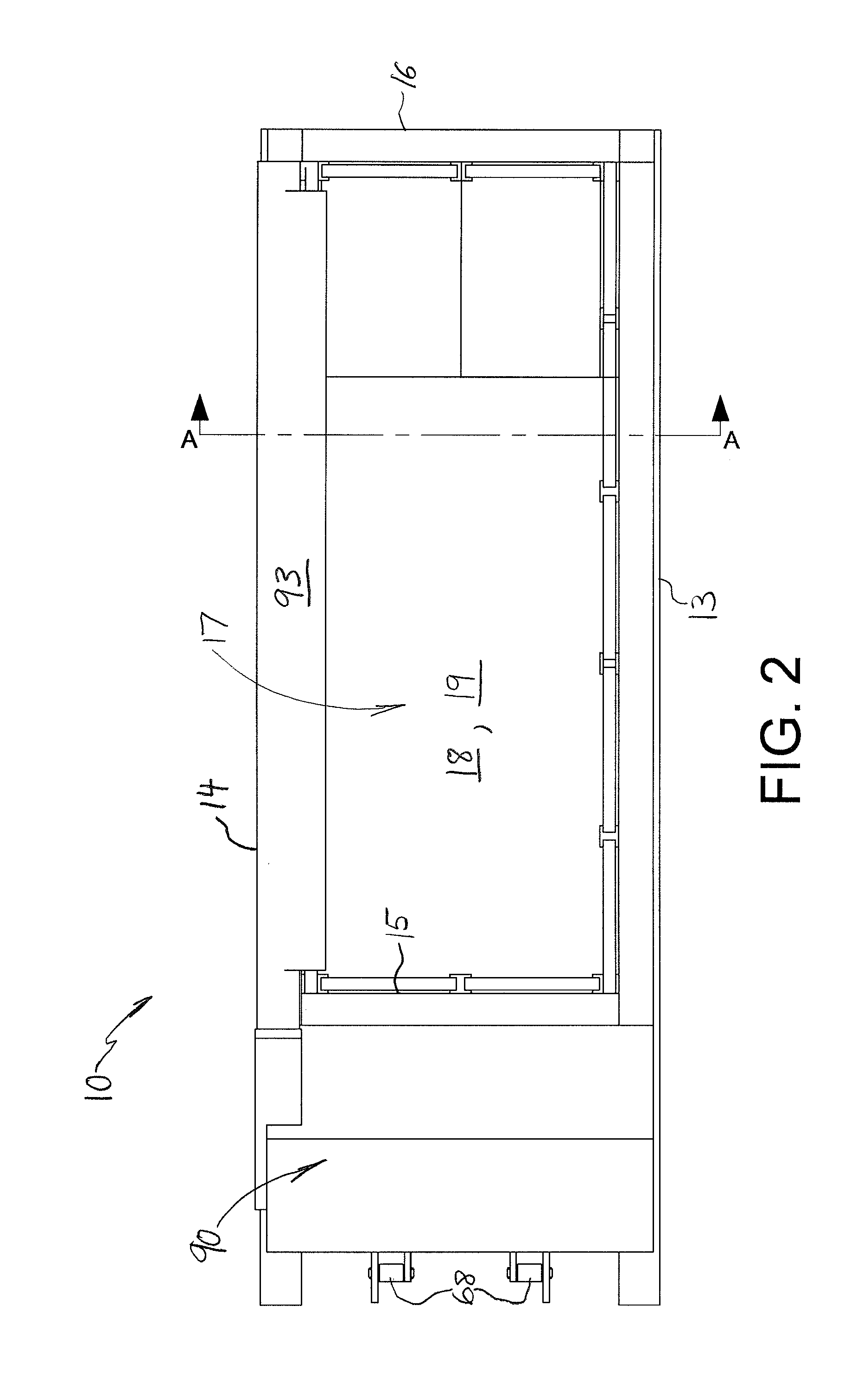
[0020]A roll-off firebox apparatus 10 formed in accordance with an embodiment of the present invention is shown in FIGS. 1-4. Apparatus 10 generally comprises a firebox 12 having a pair of longitudinal side walls 13 and 14, a front wall 15 and a rear wall 16 cooperating to define a combustion chamber 17 having and open top 18 and an open bottom 19. Rear wall 16 may be formed by double doors 16A and 16B which are each hinged along one side to open outwardly. During incineration, the ground effectively forms the bottom of combustion chamber 17. Each wall 13-15 is lined on the inside with a layer of refractory material in the form of refractory panels 20. The inside of each door 16A, 16B is similarly lined with a refractory panel 22. Each panel 20, 22 includes a steel sub-frame 24, 26 thereabout. The firebox structure described above may be manufactured as taught in commonly-owned U.S. Pat. No. 5,415,113, which is incorporated herein by reference in its entirety.

[0021]Each panel / sub-fr...


PUM


Abstract

A firebox apparatus is adapted for transport on a vehicle having a roll-off hoist mechanism by providing parallel guides on the underside of a supporting skid assembly of the firebox apparatus for engaging siderails of a tiltable roll-off track of the hoist mechanism, and by providing reinforced front and rear portions connecting parallel longitudinal skid members to maintain an opening at the bottom of the firebox apparatus yet make the firebox apparatus sufficiently sturdy to withstand loads encountered during loading an unloading from the transport vehicle. The firebox apparatus includes an air curtain system for limiting pollution resulting from incineration of waste. The present invention enables easy installation and removal of the firebox apparatus in crowded environments, such as urban environments, to cleanly burn waste.

Description

FIELD OF THE INVENTION[0001]The present invention relates to the field of waste disposal, and in particular waste disposal by incineration.BACKGROUND OF THE INVENTION[0002]Incinerating waste is a known alternative to burying waste or transporting it to another location. In order to reduce ash and smoke released during waste incineration (particulate release), a flow of high velocity air has been used to provide an “air curtain” over a fire pit or firebox in which the waste is burned. U.S. Pat. Nos. 4,756,258 and 5,415,113 describe portable apparatus for air curtain incineration. The former patent teaches a fan and manifold assembly that can towed to the edge of a fire pit, such as may be found at a landfill site. The latter patent teaches a firebox apparatus including a fan and manifold assembly mounted on a support skid for transport on a flatbed truck to a desired site, for example a development site where vegetation is being cleared.[0003]Neither of the portable solutions mention...

Claims


Application Information

Patent Timeline
IPC IPC(8): F23G5/40
CPCF23G5/40
Inventor O'CONNOR, BRIAN M.
Owner AIR BURNERS
Learn More