WirelessTag Tracer Method and Apparatus

a tracer and wireless technology, applied in the field of apparatus and methods to track fluids, can solve the problems of preventing the use of radioactive tracers, unable both methods can be imprecise and/or fail to achieve the intended purpose,

Inactive Publication Date: 2009-08-27
VERRET ROBIN JAMES
View PDF2 Cites 136 Cited by
  • Summary
  • Abstract
  • Description
  • Claims
  • Application Information

AI Technical Summary

Problems solved by technology

Both of these methods can be imprecise and/or fail their intended purpose.
In the U.S., for example, stringent Occ...

Method used


Image

  • WirelessTag Tracer Method and Apparatus
  • WirelessTag Tracer Method and Apparatus
  • WirelessTag Tracer Method and Apparatus

Examples


Embodiment Construction

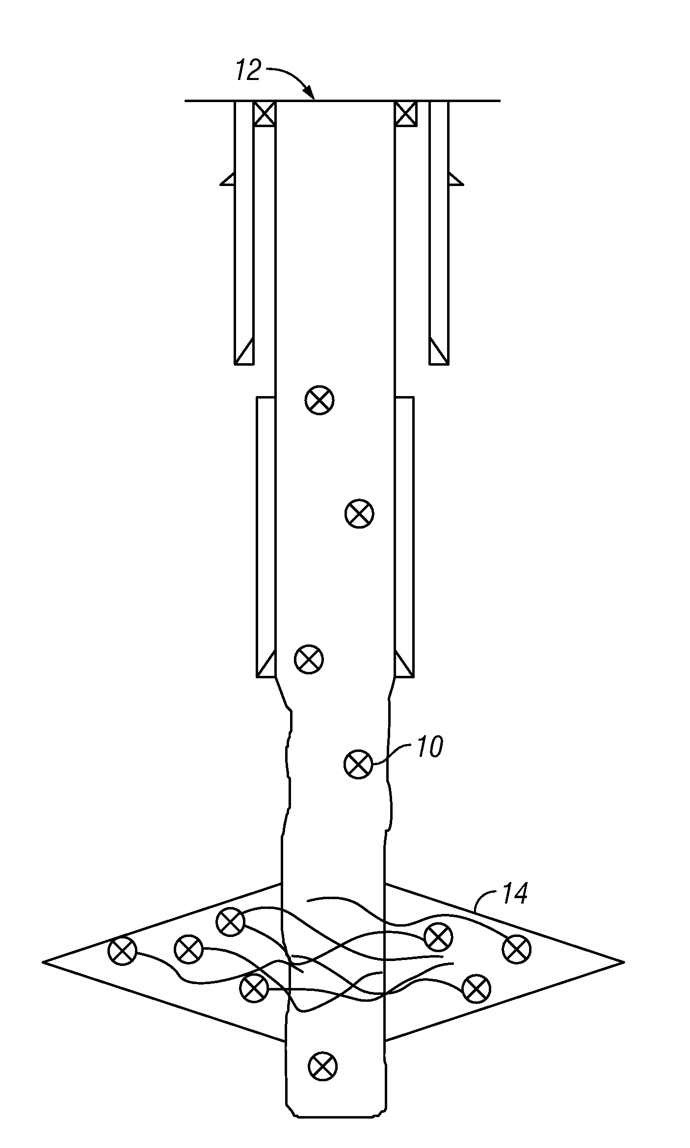
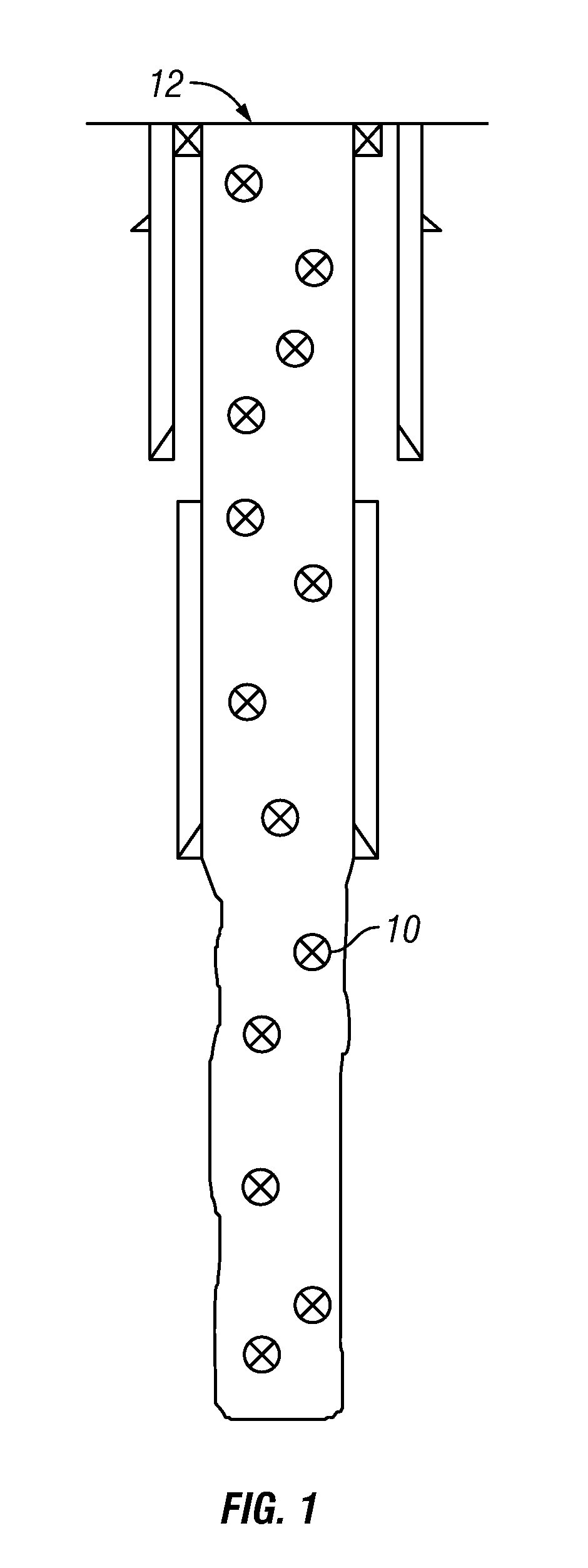
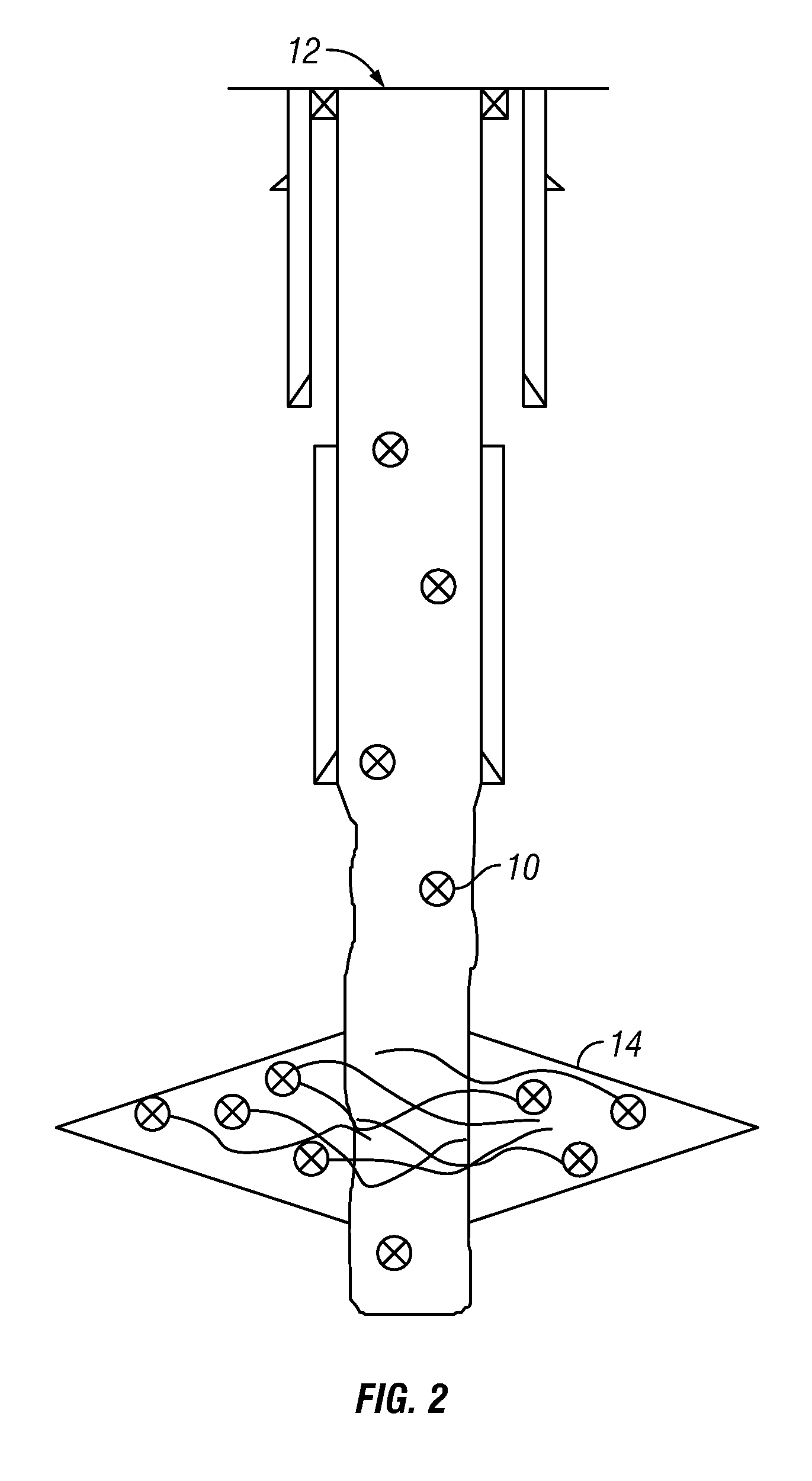
[0023]The invention relates generally to an apparatus and method of tracking a fluid in a wellbore with at least one electronic tracking device entrained therein; or more particularly, with at least one wireless identification (WID) tag entrained therein.

[0024]In one embodiment the WID tag can be a radio frequency identification (RFID) tag. Generally, an RFID tag is a device that transmits identification information to a reader, also referred to as an interrogator. RFID tags typically include an antenna and means to transmit a signal corresponding to a data representation, e.g., a microchip or piezoelectric crystals with reflectors on the surface thereof. RFID technology was previously claimed in U.S. Pat. No. 3,054,100, herein incorporated by reference.

[0025]In another alternative or additional embodiment, the WID tag can be a long wavelength identification (LW) tag. In an embodiment, the LW tag can operate at a long wavelength such as less than about 450 KHz, low speed such as abo...


PUM


Abstract

A fluid can be tracked in a wellbore utilizing at least one WID tag, such as an LW tag or an RFID tag, entrained in the fluid. A WID tag reader can be disposed and/or displaced in the wellbore, for example, on a drill string or a casing string. A reader can be utilized to locate the at least one WID tag in the wellbore. A reader can be housed in a drill string sub. A fluid entrained with at least one WID tag can be utilized as a tracer fluid. A WID tag can be entrained in cement or a drilling or fracture fluid.

Description

CROSS REFERENCE TO RELATED APPLICATIONS[0001]This application is a continuation-in-part of U.S. Ser. No. 12 / 145,726, filed Jun. 25, 2008, which is a nonprovisional of U.S. 60 / 945,968, filed Jun. 25, 2007.BACKGROUND[0002]The invention relates generally to an apparatus and method to track a fluid with a wireless tracking device entrained in the fluid.[0003]It can be desirable to track a fluid in a wellbore, e.g., a wellbore in a formation for the recovery of hydrocarbons. Tracking a fluid can include determining the location of a fluid loss zone and / or the location of a fluid itself, e.g., drilling mud, cement, etc., in the wellbore. One way of identifying a possible location of a loss zone, e.g., lost circulation, is to use a noise log, which measures any increase in movement or activity in a wellbore based on the change in tone or volume in the noise of flowing fluid at a certain depth, using specialized logging tools. Another method of identifying a possible location of a loss zone...

Claims


Application Information

Patent Timeline
IPC IPC(8): E21B47/00E21B47/10G01V3/00
CPCE21B47/1015E21B47/10E21B47/005E21B47/11
Inventor VERRET, ROBIN J.KILCHRIST, MICHAEL J.
Owner VERRET ROBIN JAMES
Why Eureka
Try Eureka