Banknote handling apparatus

a technology for handling apparatuses and banknotes, applied in the direction of pile separation, transportation and packaging, instruments, etc., can solve the problems of difficult miniaturization of the entire apparatus, large space requirements, and easy occurrence of dead space in the apparatus, so as to achieve more reliable release of the jam

Inactive Publication Date: 2009-08-27
GLORY KOGYO KK
View PDF0 Cites 18 Cited by
  • Summary
  • Abstract
  • Description
  • Claims
  • Application Information

AI Technical Summary

Benefits of technology

[0054]The introduction unit, release unit, collection unit, and reject unit in this banknote-handling apparatus are also arranged at the diametral opposite side from the storage units with respect to the conveyance drum. This arrangement, in turn, makes it possible to lay out internal components of the apparatus in even more rational collective form, and to further miniaturize the entire apparatus.
[0055]In addition, if a jam of a received banknote is detected in the present banknote-handling apparatus, a banknote conveyance force thereof that is generated by the conveyance drum can be increased in a relative fashion by reducing a rotating speed of the conveyance drum, to achieve more reliable release of the jam.

Problems solved by technology

The conventional banknote handling apparatuses using such a belt type of conveyance means have the problems below.
Accordingly, the driving device needs to be dimensionally large, which makes it difficult to miniaturize the entire apparatus.
To satisfy the above requirement, therefore, a considerable deal of space is required and as a result, a dead space becomes prone to occur in the apparatus.
This is another factor that makes the miniaturization of the entire apparatus difficult.
In that case, however, the elastic belt needs supporting in bent form by using a number of idler rollers or the like, which will increase not only costs, but also conveyance loads, thus resulting in a further dimensional increase in the driving device.
Therefore, this countermeasure is not necessarily effective.

Method used


Image

  • Banknote handling apparatus
  • Banknote handling apparatus
  • Banknote handling apparatus

Examples


Embodiment Construction

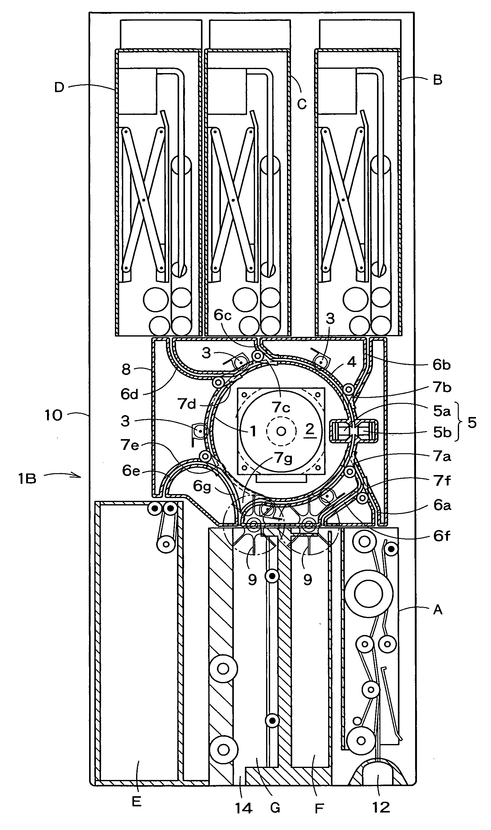
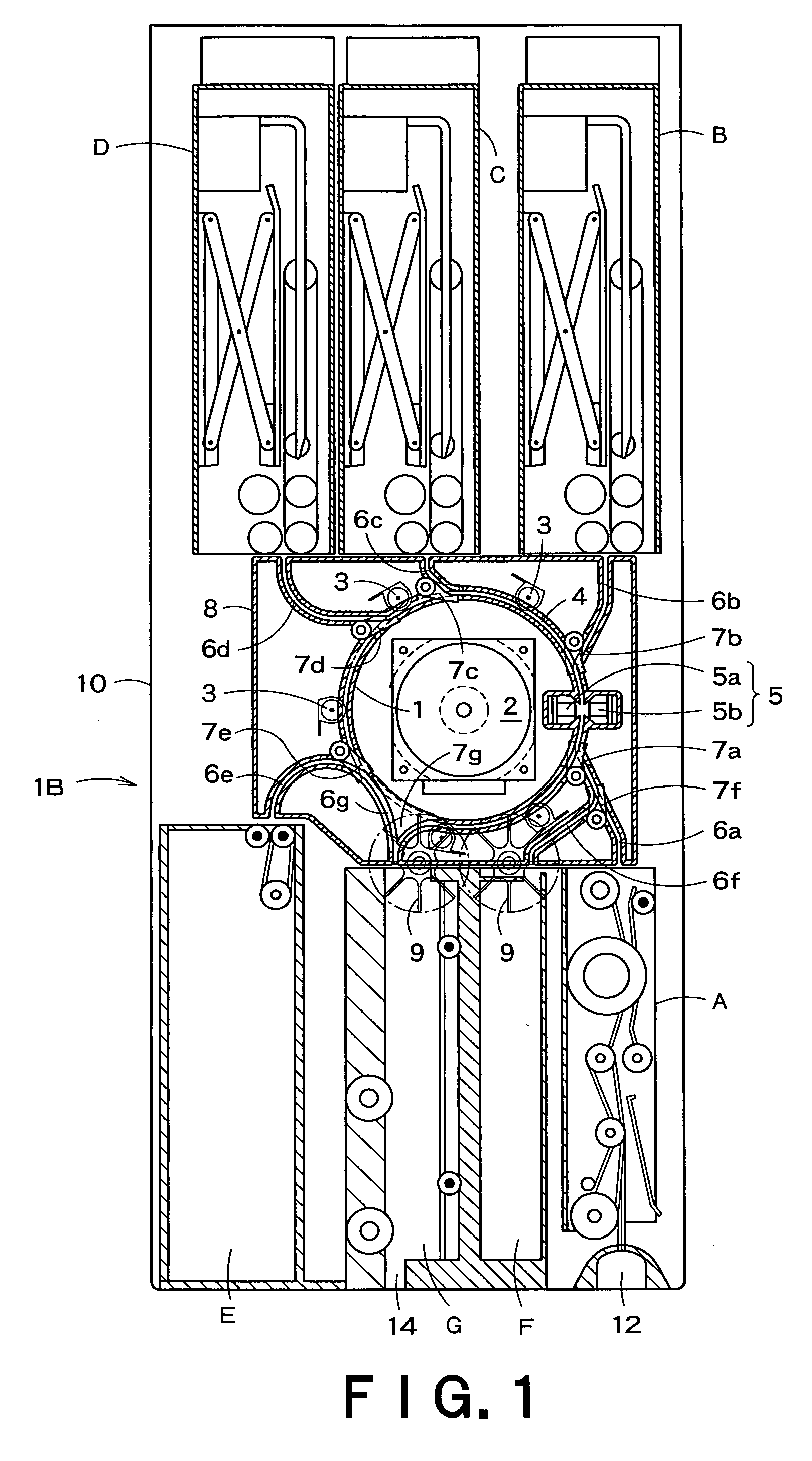
[0093]An embodiment of the present invention is described below referring to the accompanying drawings. More specifically, an overall configuration, route changer, banknote storage units, control system, total operation, operationally advantageous effects, and modifications of a banknote handling apparatus according to the present embodiment are described in that order. In the description of the route changer and the storage units, respective description items are further divided into sub-items, that is, a further detailed configuration, characteristic function and effect, and modifications.

{Overall Configuration}

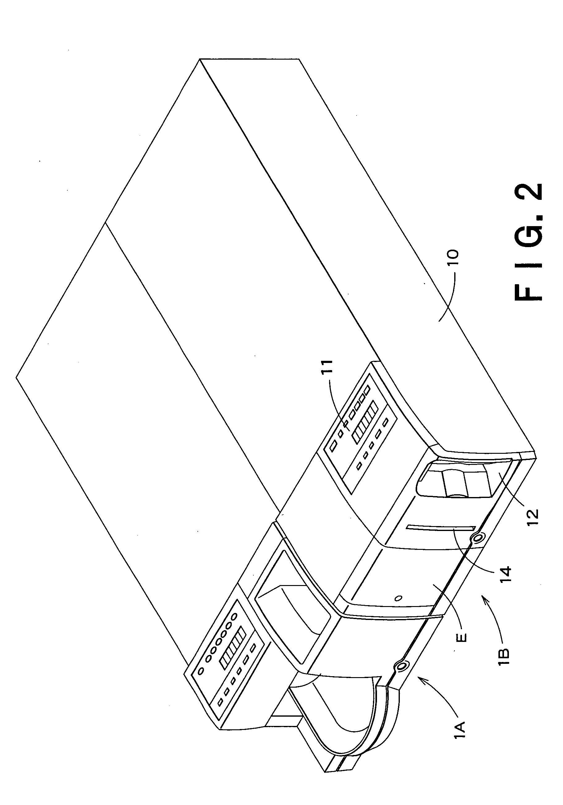
[0094]First, the overall configuration of the banknote-handling apparatus for receiving and disbursing banknote is described referring to FIGS. 1 to 4.

[0095]The banknote handling apparatus 1B in FIG. 1 is used in combination with a coin handling apparatus 1A adapted to receive and disburse coins, as shown in FIG. 2, for example. In that case, the coin handling apparatus 1A ...


PUM

PropertyMeasurementUnit
circumferential lengthaaaaaaaaaa
lengthaaaaaaaaaa
rotating speedaaaaaaaaaa

Abstract

This banknote handling apparatus includes multiple units (A to G) each for banknote receiving, disbursing, and the like, and a conveyance drum (1) with a circumferential length greater than length of the longest banknote. Multiple pressure rollers (3) are each pressed against an outer surface of the drum. A circling route (4) for banknote conveyance, having a discrimination sensor (5), is formed around the outer surface of the drum. The units (A-G) are connected to the circling conveyance route by their respective interconnecting route (6a-6g) for banknote conveyance. A route changer is provided for conducting route changes from the circling conveyance route to each interconnecting conveyance route, and vice versa. A rotational direction of a rotary drum (1a) during the conveyance of a banknote into either of the units (B, C, D), and a rotational direction of the drum (1a) during the conveyance of a banknote into either of the units (A, E, F, G) arranged at an opposite side from the units in a diametral direction of the conveyance drum, are also made opposite to each other.

Description

TECHNICAL FIELD[0001]The present invention relates to a banknote handling apparatus for receiving and disbursing banknotes, the apparatus having a sensor on a banknote conveyance route to discriminate denominations of the banknotes.BACKGROUND ART[0002]Such a banknote handling apparatus is usually constructed so as to convey banknotes to a storage unit or the like by means of a stretched elastic belt. For example, JP-A-2001-143128 relating to the applicant for the present invention discloses means for conveying banknotes by using a belt linearly stretched between pulleys of substantially the same diameter.[0003]The conventional banknote handling apparatuses using such a belt type of conveyance means have the problems below.[0004]First, there is a need to drive the conveyance belt while applying tension to a level at which is obtainable a gripping force that does not cause slipping of the banknote conveyed. Driving the elastic belt in defiance of such a tensile load requires a very hi...

Claims


Application Information

Patent Timeline
Patent Type & Authority Applications(United States)
IPC IPC(8): G07F7/04
CPCB65H3/44B65H29/54G07D11/0003B65H2701/1912B65H2513/42B65H2513/41B65H29/58B65H31/24B65H83/025B65H2404/40B65H2404/612B65H2405/33B65H2220/02B65H2220/11B65H2220/01B65H2301/321B65H2301/4482G07D11/10B65H2404/64G07D11/16G07D2211/00
Inventor OIE, YOSHIROTONE, HIROSHITABATA, RYUICHI
Owner GLORY KOGYO KK
Why Eureka
Try Eureka