

LED Module
a technology of led lamps and modules, applied in the field of led modules, can solve the problems of difficult to dissipate heat, damage to led lamps, and only a few millimeter gap, and achieve the effect of enhancing the brightness of led lamps
- Summary
- Abstract
- Description
- Claims
- Application Information
AI Technical Summary
Benefits of technology
Problems solved by technology
Method used
Image

Examples
Embodiment Construction
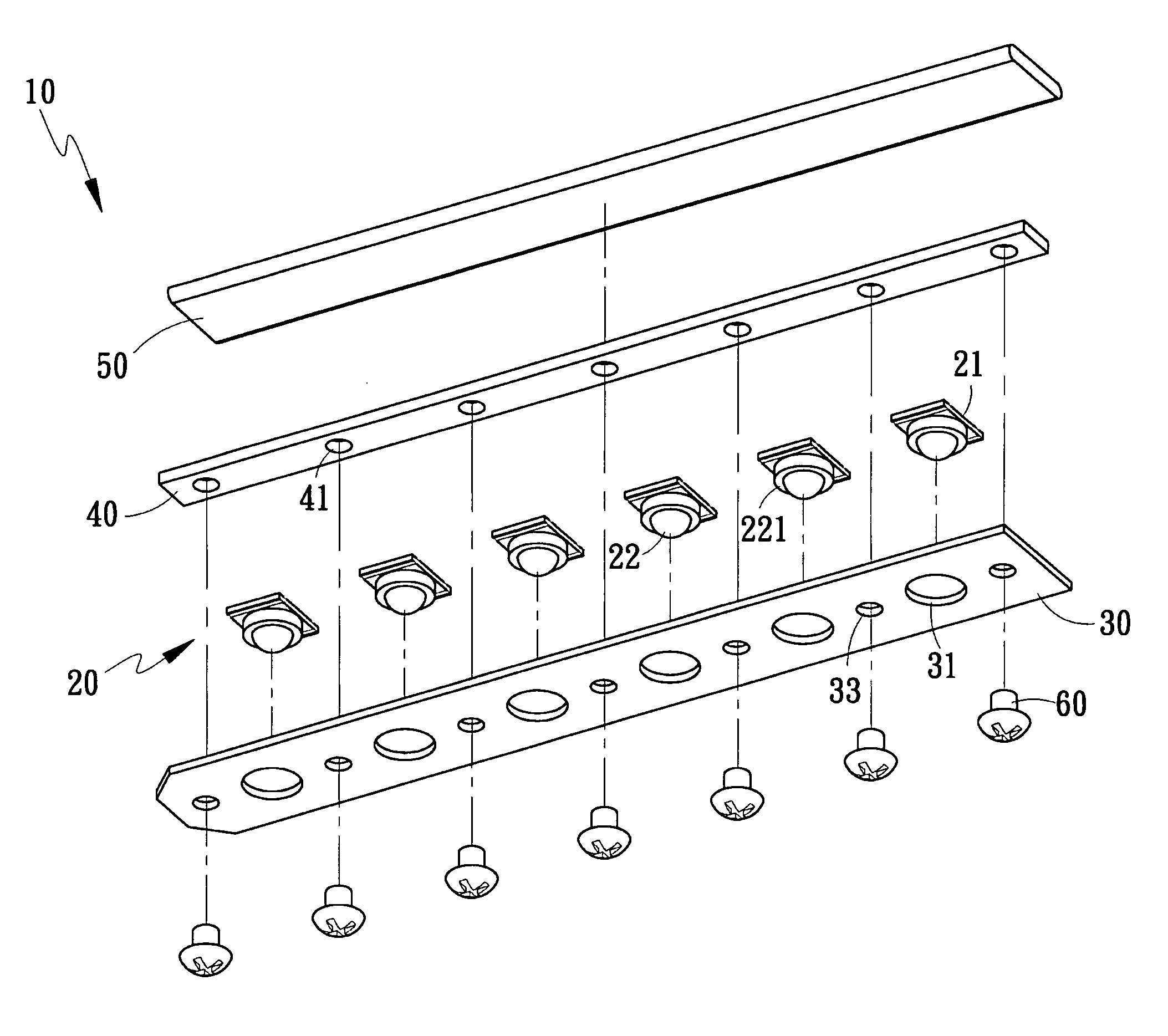
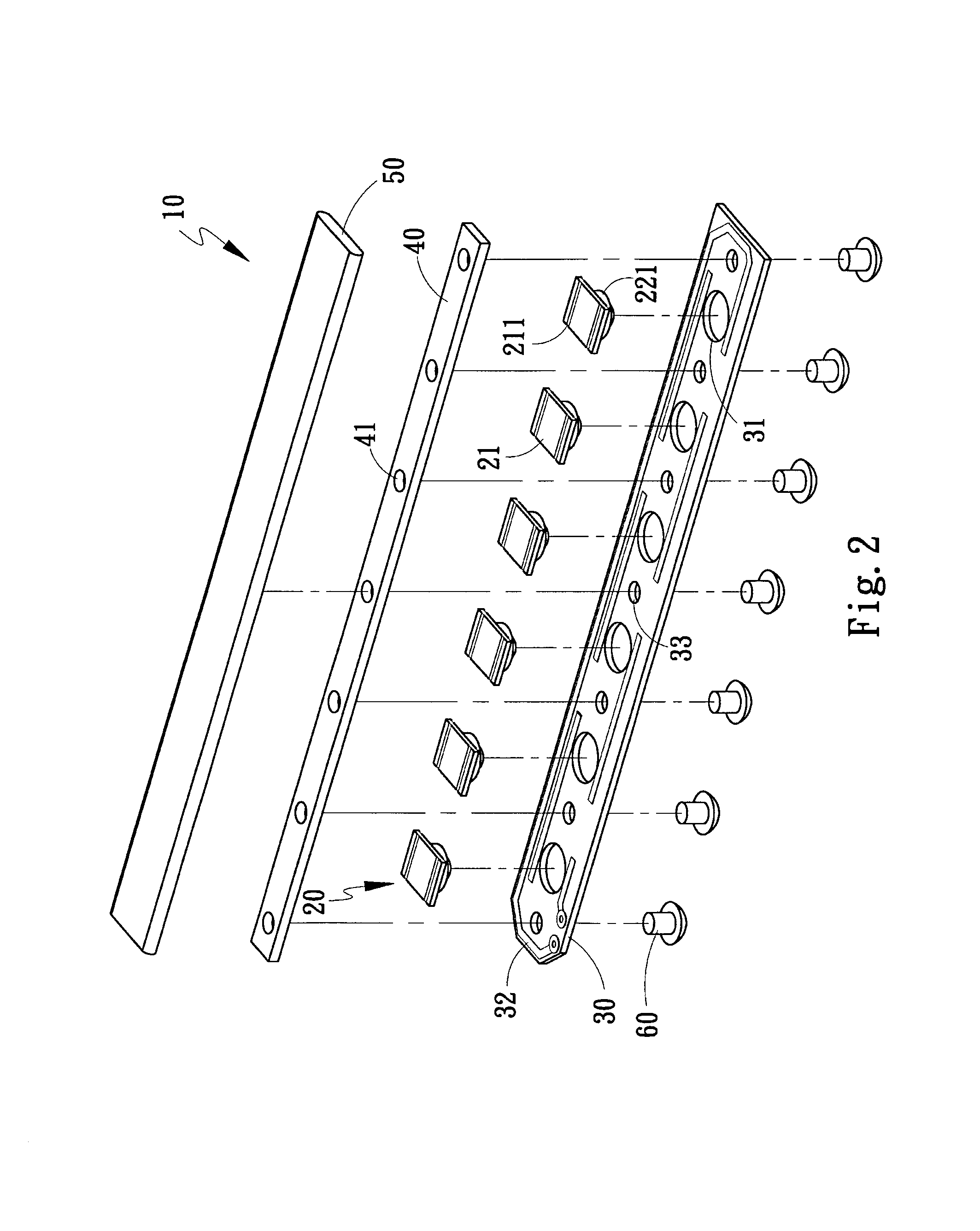
[0021]Refer to FIG. 2 and FIG. 3. The present invention discloses an LED (Light Emitting Diode) module 10, which comprises: a plurality of LED lamps 20, a plurality of baseplates 30, a plurality of heat-conduction blocks 40, a plurality of heat-conduction elements 50, and a plurality of fixing elements 60. The LED lamp 20 has an electrode plate 21 on one side thereof and has an LED 22 on the other side thereof. One face of the electrode plate 21 has two electrodes 211 respectively arranged in two edges thereof. A protection ring 221 annularly surrounds the LED 22. The baseplate 30 is a PCB (Printed Circuit Board) having circuits thereon. The baseplate 30 has a plurality of via-holes 31, and the LED lamps 20 are inlaid into the via-holes 31. The baseplate 30 has cascade circuits 32 to cascade the LED lamps 20 to enhance brightness. The baseplate 30 also has a plurality of through-holes 33, and the fixing elements 60 are inserted through the through-holes 33 to fasten the baseplate 30...
PUM
 Abstract
Description
Claims
Application Information