However, gravito-electric plants would be much smaller; their location would not be restricted to suitable water elevations, and the plants and their produced energy would be much less expensive.
There is no other physical effect available.
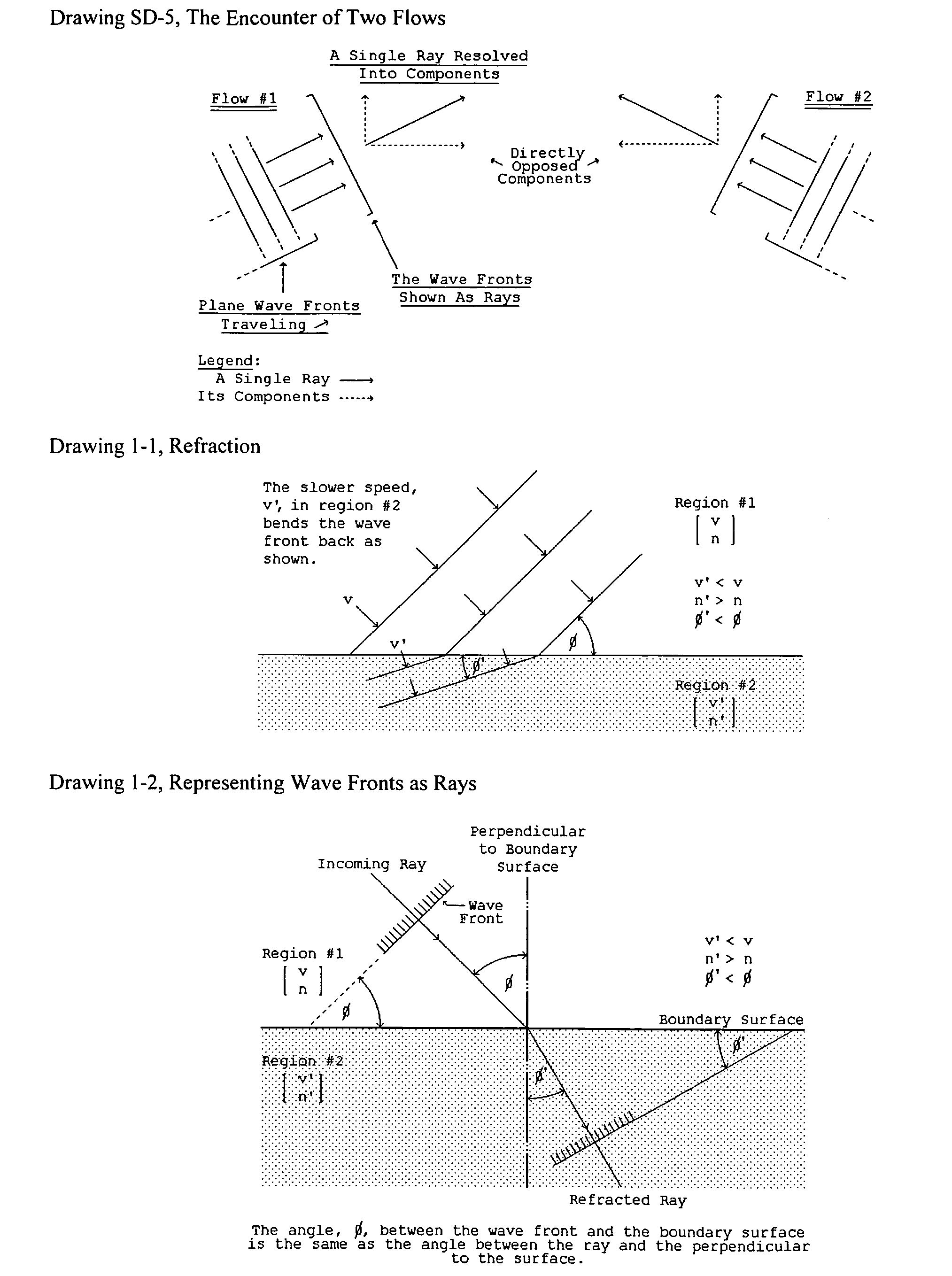
Two such universal flows directly encountering each other “head on” [flowing exactly toward each other] interfere with the other, that is each slows the flow of the other.
But, gravitation has remained beyond our control.
The behavior of light is complex and involves some aspects of its behavior that U-wave flow does not.
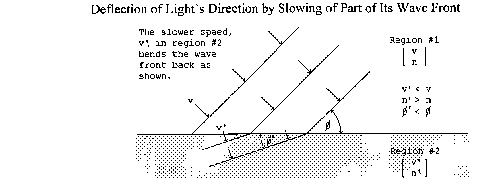
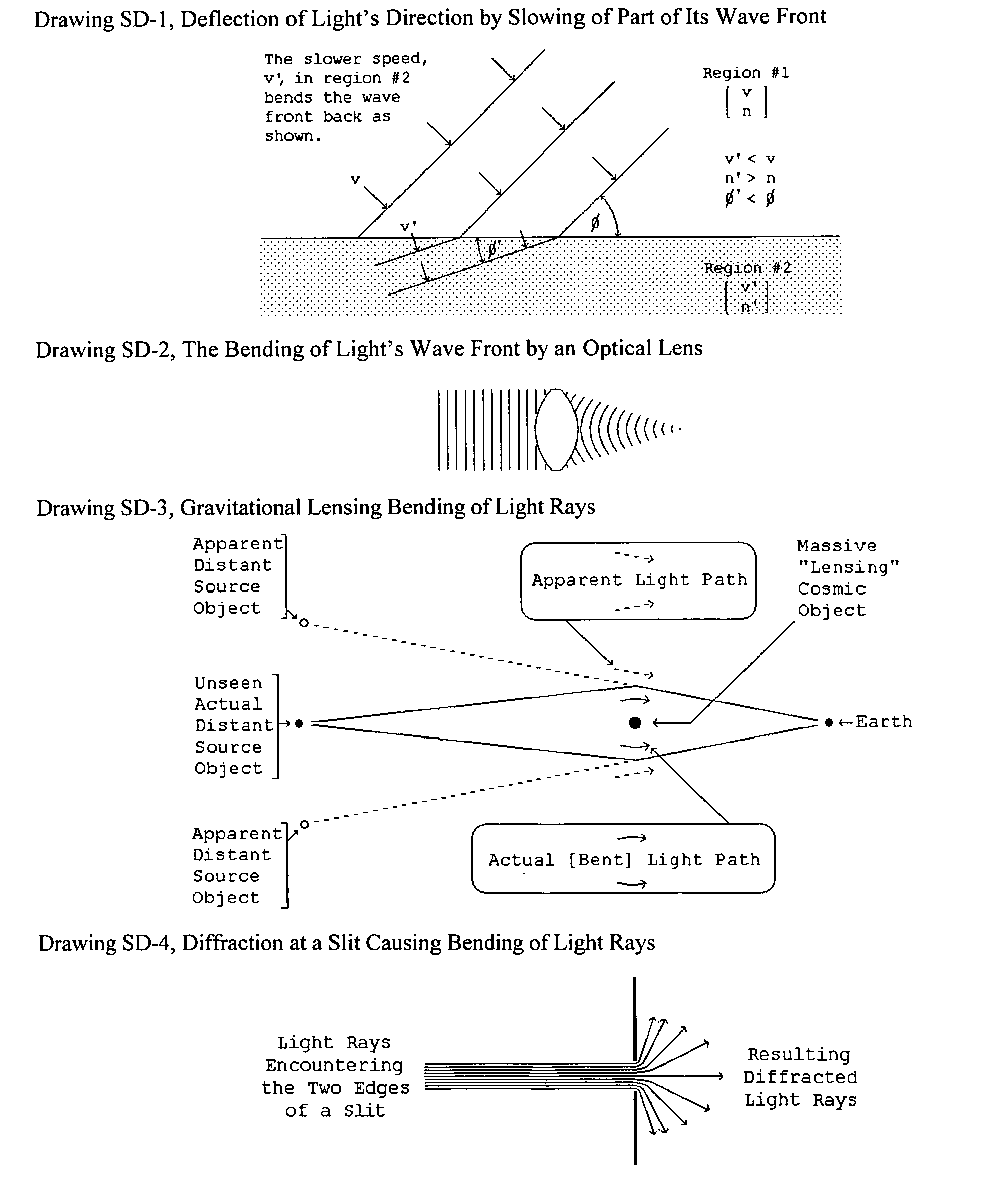
That interaction tends to slow the speed of the light while traversing the matter.
If that were not the case focusing of light would be severely impaired for the initial result of the focusing would be quickly blurred by the spreading out of the light of each “
wavelet”.
Not all surfaces support reflection.
As presented in The Origin and Its Meaning that effect creates an imbalance in the core's propagation, an imbalance that cannot exist.
As a result, the index of
refraction of actual light is of little use in analyzing U-wave behavior.
It would thus appear that the medium flow concentration of gravitation at the Earth's surface is so immensely greater than the ambient flow in local matter that no useful slowing of the Earth's gravitational flow can be directly effected by a modest amount of matter.
Thus the direct use of natural local matter to deflect or control gravitational U-
waves appears to be self-defeating.
But in the case of
light diffraction the slit edge is opaque and light travel through it is not applicable.
The amount is determined solely by the amount of matter and any benefit from that form of control is more than offset by the
disadvantage of the major amount of additional matter required to produce an effect.
The problem with this method is that a practical implementation that so operates on U-
waves, as compared to how it operates on a light imprint on them, appears to be quite difficult.
Uniform slowing of U-
waves in the amount here required would, pending further developments, appear to be impossible.
One of the problems in using reflection or
refraction to manage the direction of U-waves is that U-waves naturally penetrate and permeate all matter.
Thus the case of x-rays is somewhat intermediate between that of easily managed light and difficult-to-manage U-waves.
However, even this “
grazing incidence” type of propagation direction control will not work for U-waves.
The problem is that the nearness to the “edge” must be not more than on the order of 10-7 meters for even
a moderate amount of deflection of Earth's surface local ambient U-waves, and those are 1015 times weaker than Earth's gravitational U-waves.
The cubic
crystal deflector should produce major, reduction in the gravitational action on whatever is above it, but it should not necessarily succeed in totally removing that action.
The problem now is to quantify the deflection of those U-waves.
But, U-waves cannot reflect.
Such a fine tilt angle and its precision are unlikely if not impossible to set up.
On the other hand, the human passengers and some kinds of cargo would react poorly to experiencing gravity acting in other than the normal surface-of-the-Earth manner.
Of course, the transition to gravito-
electric energy would involve major economic and social changes with the associated political conflicts and problems.
It would thus appear that the medium flow concentration of
Earth surface gravity is so immensely greater than the ambient flow in local matter that no useful slowing of the Earth's gravitational flow can be directly effected by a modest amount of matter.
Thus the direct use of natural local matter itself to deflect, refract, or otherwise affect or control gravitational U-waves appears to be self-defeating in that the amount of matter needed to produce a useful U-wave medium concentration would itself be an immense gravitating
mass.
However, the setting of such a minute angle and offset, much less doing so sufficiently precisely, is not practical and probably impossible.
The inverse, requiring a perfect integral sub-multiple relationship would be essentially impossible in practice.
On the other hand, the chance that some particular achieved tilt angle and offset requires more
layers of cubic
crystal than the “fundamental case” because of inefficient scheduling of successive positions is a significant consideration.
The effects of temperature variation in the
Silicon cubic crystal and various random vibrations within it would overwhelm such a minute setting.
For that reason alone, the setting and maintaining of so precise an objective offset is impractical.
The net effect of this behavior of the atoms is that the original concept is unworkable.
The effects would overwhelm such a minute setting, which is probably too minute to accurately set in any case.
Second, the issue of the tilt angle and offset that it produces now is that of properly staggering the atomic vibration ranges of the atoms in each layer that same range amount.
Another precision issue is that of the orientation of the cubic crystal.
Using commercial wafers of that type with their very small thickness would be impractical.
But, the losses of the
water flow to friction and turbulence increase as the velocity of the flow increases.
In general the exceptions tend to have problems of potential corrosiveness or poisoning.
The use of such particles might result in unacceptable levels of wear and damage to the
turbine mechanisms.
It would appear that methods to increase output by increased
working fluid density are not, for gravito-
electric power stations, as economically viable as accomplishing equivalent output increase through larger sized gravito-electric units or a greater number of them in parallel.
Using commercial wafers of that type would be impractical given the actual requirements.


