Two-material separable insulated connector

a technology of separable insulated connectors and connectors, which is applied in the direction of coupling device connections, other domestic articles, and coupling device details, etc., can solve the problems of soft shells and inserts that may not provide strength and durability, and the separable insulated connectors face can be corroded by discharg

Active Publication Date: 2009-08-27
EATON INTELLIGENT POWER LIMITED
View PDF102 Cites 18 Cited by
  • Summary
  • Abstract
  • Description
  • Claims
  • Application Information

AI Technical Summary

Benefits of technology

[0018]In yet another aspect, the invention provides a separable insulated connector that includes at least one stiff area and one soft area. The separable insulated connector can comprise an elbow connector, a T-body connector, or any other type of separable insulated connector known to those having ordinary skill in the art and having the benefit of the present disclosure. The stiff and soft areas can be located on a shell of the separable insulated connector or on a semi-conductive insert disposed within the separable insulated connector. Alternatively, the separable insulated connector can include a shell and a semi-conductive insert, both of which can include a stiff area and a soft area. By including both a stiff area and soft area, the separable insulated connector can capitalize on the advantages associated with both stiff and soft materials in the manufacture of conventional separable insulated connectors.

Problems solved by technology

This discharge can occur if there is a voltage drop across the air gaps, and the discharge can corrode the rubber materials often used to make the separable insulated connector.
One particular difficulty that manufacturers of separable insulated connectors face is in determining how flexible a material (such as EPDM rubber) to use in manufacturing the components of a connector.
This difficulty arises because a soft shell or insert has certain advantages and disadvantages when compared to a stiff shell or insert.
However, soft shells and inserts may not provide the strength and durability that is desirable for separable insulated connectors.
A soft shell or insert may be more likely to warp in case of a power surge or fault current, and may be more likely to accidentally disconnect from the cable and / or energy distribution component.
Additionally, a soft shell or insert may not be easily moved, disconnected, or adjusted without tearing or causing other damage to the connector.
With such an approach, however, the shells and inserts also retain some of the disadvantages of a stiff or soft material, and fail to maximize the advantages of each material.

Method used


Image

  • Two-material separable insulated connector
  • Two-material separable insulated connector
  • Two-material separable insulated connector

Examples


Embodiment Construction

[0023]The following description of exemplary embodiments refers to the attached drawings, in which like numerals indicate like elements throughout the several figures.

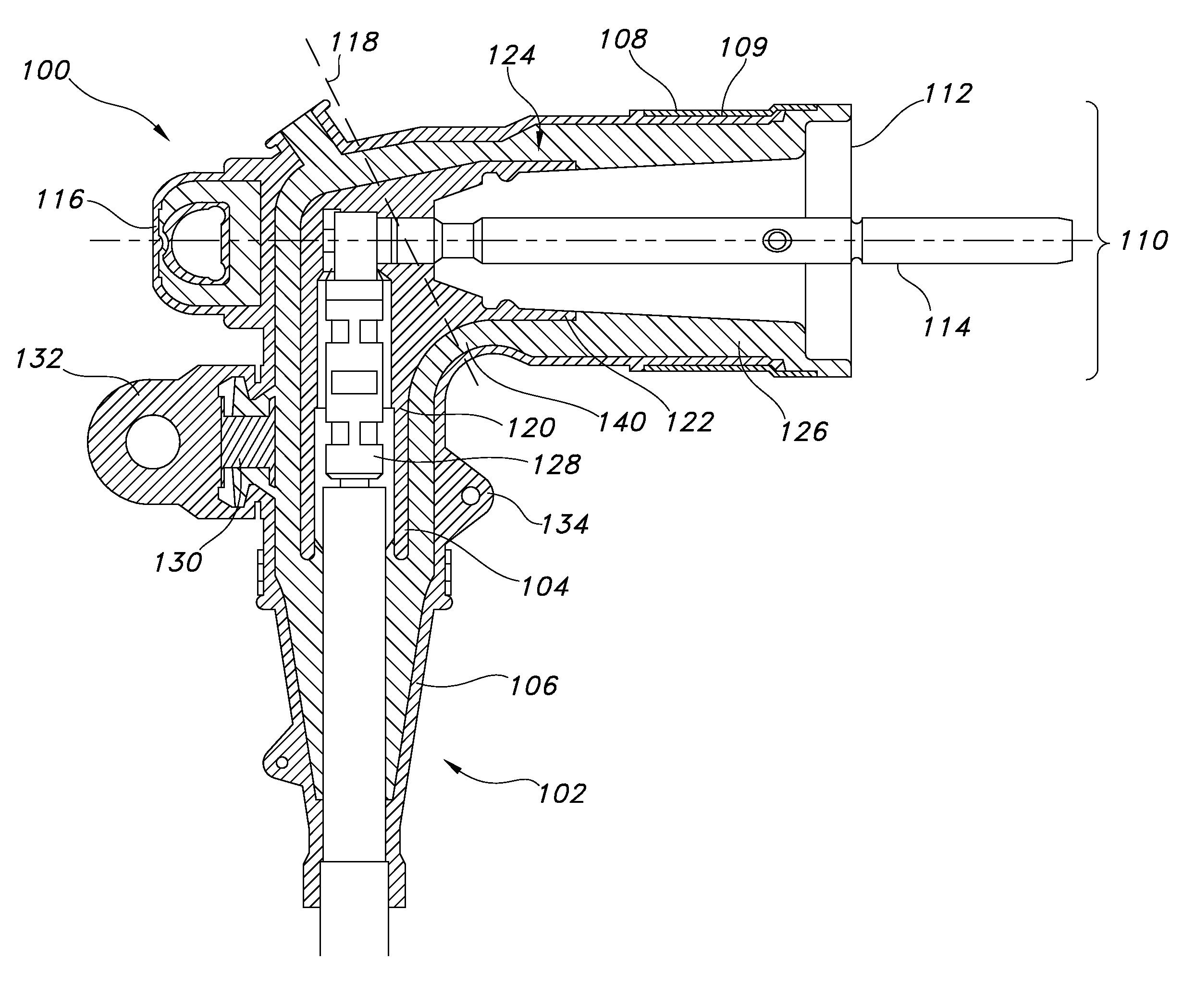
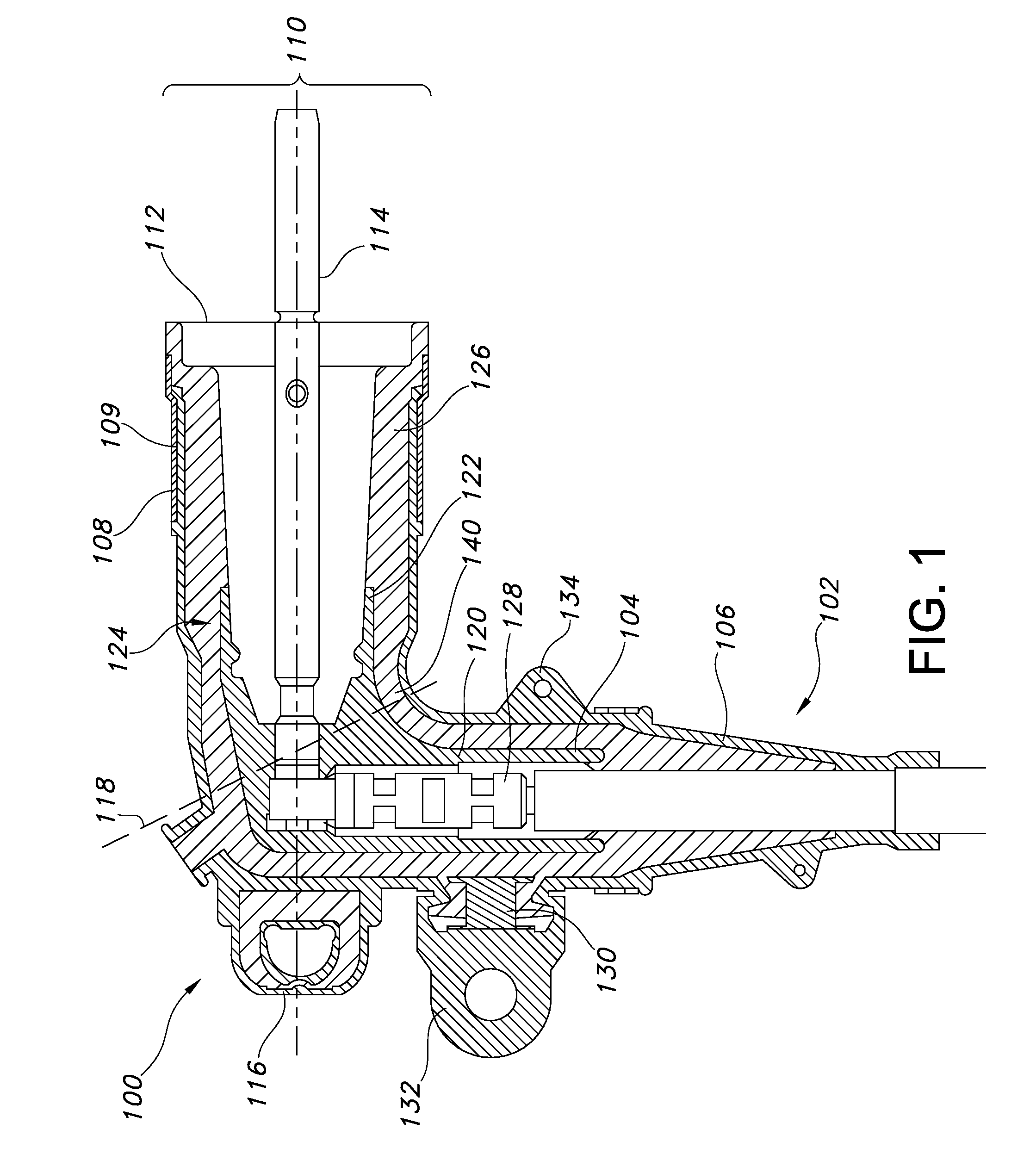
[0024]FIG. 1 is a cross-sectional side view of an elbow connector 100 having a stiff area 106 and a soft area 108, according to an exemplary embodiment. The elbow connector 100 includes a shell 102 that includes a bushing entrance 110 having an opening 112. In the illustrated embodiment, a probe 114 is partially disposed within the opening 112 of the bushing entrance 110. In alternative exemplary embodiments, the opening 112 can be used to attach the elbow connector 100 to a switchgear, transformer, or other energy distribution component to which the elbow connector 100 may be connected. In an exemplary embodiment, as shown in FIG. 1, the probe 114 or other similar bushing may be inserted into the opening 112, and then the probe 114 may be inserted into an energy distribution component.

[0025]The shell 102 of the elbow ...


PUM

PropertyMeasurementUnit
elongationaaaaaaaaaa
elongation percentageaaaaaaaaaa

Abstract

Stiff and soft materials each provide certain advantages when used in the manufacture of separable insulated connectors, such as elbow and T-body connectors. Utilizing a shell or an insert that includes one section made from a stiff material and one section made from a soft material can provide a separable insulated connector that capitalizes on the advantages associated with both types of materials. The stiff materials and soft materials can be placed strategically on the shell or insert of the separable insulated connector to maximize the advantages of each material. For example, the stiff material can be used to form a section of the separable insulated connector where strength and durability is most desirable, and conversely, the soft material can be used to form a section of the connector where flexibility is desirable.

Description

CROSS REFERENCE TO RELATED APPLICATIONS[0001]This patent application claims priority to U.S. patent application Ser. No. 11 / 809,508, entitled “Jacket Sleeve with Grippable Tabs for a Cable Connector,” filed Jun. 1, 2007, the complete disclosure of which is hereby fully incorporated herein by reference.TECHNICAL FIELD[0002]The invention relates generally to separable insulated connectors for electric power systems. More specifically, the invention relates to a separable insulated connector made of two separate materials—a stiff material and a soft material.BACKGROUND OF THE INVENTION[0003]Separable insulated connectors provide an electric connection between components of an electric power system. More specifically, separable insulated connectors typically connect sources of energy—such as cables carrying electricity generated by a power plant—to energy distribution systems or components thereof, such as switchgears and transformers.[0004]Two common types of separable insulated connec...

Claims


Application Information

Patent Timeline
Patent Type & Authority Applications(United States)
IPC IPC(8): H01R13/46
CPCB29C45/1676B29K2023/16B29L2031/36H01R13/46Y10T29/49002H01R13/53H01R43/18Y10S439/921H01R13/504
Inventor HUGHES, DAVID CHARLESAUGUSTIA, THOMASMAKAL, JOHN MITCHELLGEBHARD, SR., MICHAEL JOHN
Owner EATON INTELLIGENT POWER LIMITED
Why Eureka
Try Eureka