Screen printer print carriage

a screen printer and print carriage technology, applied in printing presses, office printing, printing, etc., can solve the problems of difficult removal of squeegees and flood bars on the print carriages

Inactive Publication Date: 2009-09-03
REEFDALE PTY LTD
View PDF11 Cites 7 Cited by
  • Summary
  • Abstract
  • Description
  • Claims
  • Application Information

AI Technical Summary

Benefits of technology

[0009]To this end the present invention provides a squeegee or flood bar for the print carriage of a screen printing machine which consists of a mounting bracket and blade portion

Problems solved by technology

Conventionally the squeegee and flood bar on the print c

Method used


Image

  • Screen printer print carriage
  • Screen printer print carriage
  • Screen printer print carriage

Examples


Embodiment Construction

[0012]Preferred embodiments of the invention will be described with reference to the drawings in which:

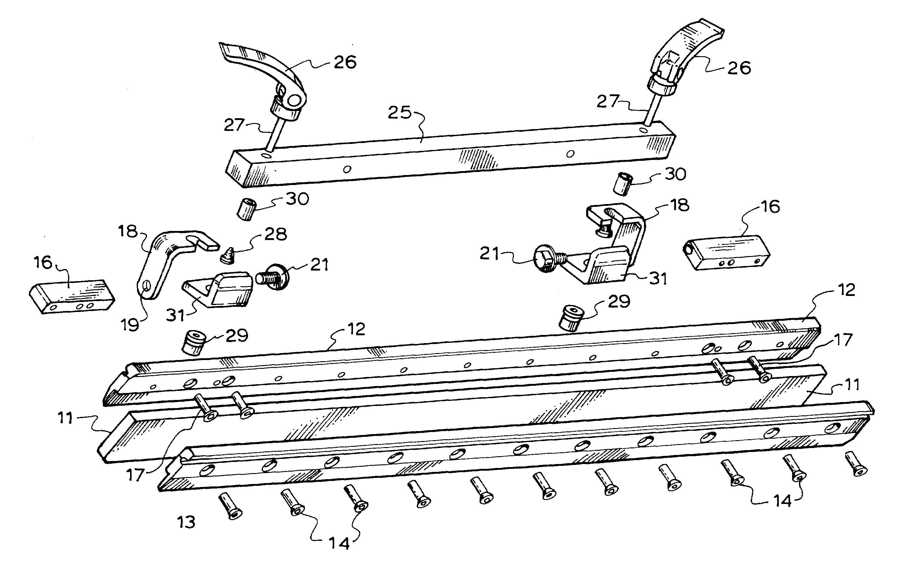
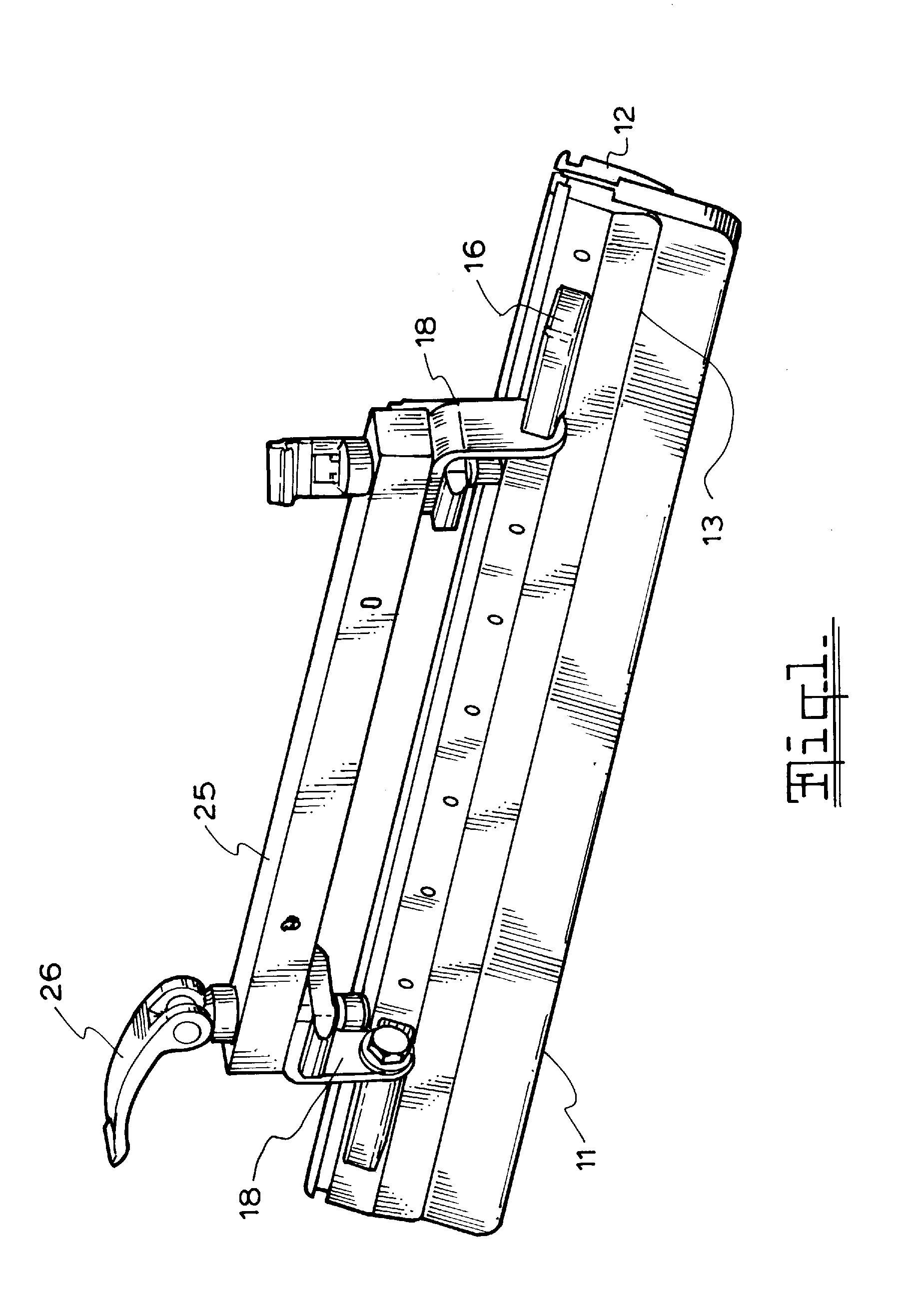
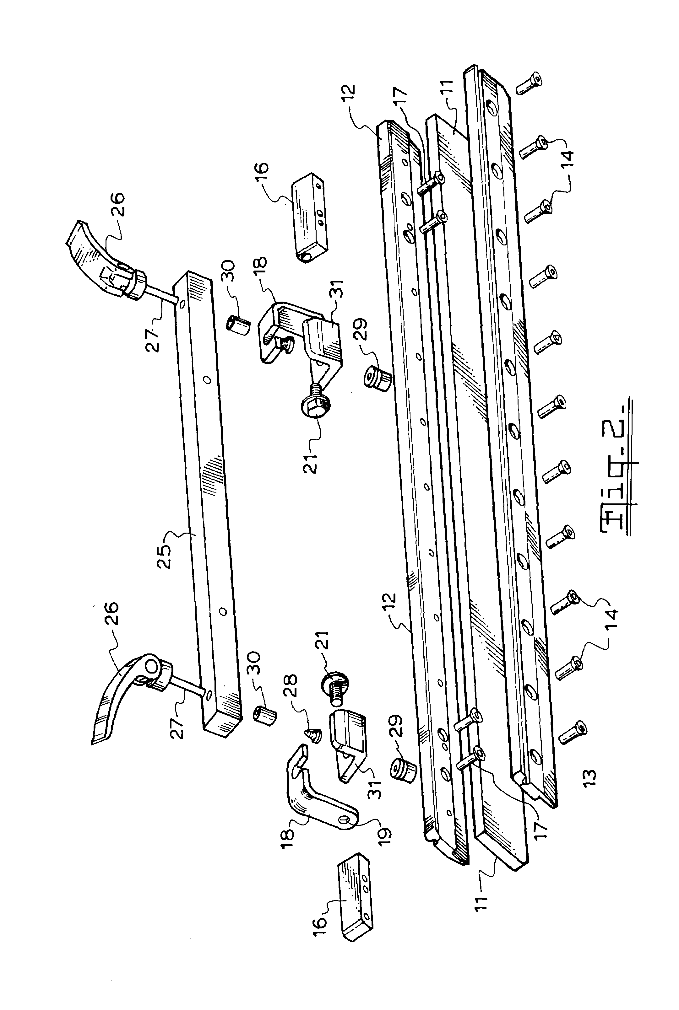
[0013]FIG. 1 is a view of a detachable squeegee blade according to an embodiment of this invention;

[0014]FIG. 2 is an exploded view of the blade of FIG. 1.

[0015]The flood bar or squeegee blade consists of the blade portion 11 and the blade holder frames 12 and 13 which are secured together with screws 14. Attached to frame 12 are the two pivot mounting blocks 16 secured by screws 17 to the frame 12. Mounting brackets 18 are secured to the mounting blocks 16 by pivot screw fasteners 21 at holes 19. The brackets 18 are L shaped and include a mounting slot 20 in the horizontal arm.

[0016]The squeegee and floodbar mounting bar 25 carries two toggle clamps 26 having shafts 27 that pass through holes in the bar 25 and carry the brass bushing 30. The end of shaft 27 carries the bracket 31 secured by adjustor nut 29. The spring 28 located about the shaft 27 provides the separating and level...


PUM


Abstract

A squeegee or flood bar for the print carriage of a screen printing machine which consists of a mounting bracket and blade portion in which the bracket portion is adapted for quick attachment and detachment to the print carriage and the bracket is attached to the blade portion on one side of the blade portion. The bracket attaches to one face of the blade near the upper edge and this offset position means that a change in the angle of inclination of the blade does not result in a large change in position of the bottom edge of the blade. The attachment means is preferably a toggle clamp on the carrier bar for the squeegee and flood bar. By simply releasing the toggle clamp the bracket and blade can be quickly removed and replaced.

Description

FIELD OF THE INVENTION[0001]This invention relates to improvements in the print carriages of carousel screen printing machinesBACKGROUND TO THE INVENTION [0002]Carousel Screen printing machines are used for screen printing of garments and utilise a plurality of fixed print heads beneath which are positioned a plurality of garment support pallets which are moveable from one print head to the next. Each print head has a carriage mounted for reciprocal movement to move the flood bar and squeegee bars over the screen.[0003]The flood bar and squeegee blades forming the print head in screen printing machines are mounted on a moving carriage with the flood bar down in the flood stroke and the squeegee down in the print stroke. The carriage is supported at both ends in a print frame and moves back and forth along the print frame. U.S. Pat. No. 5,189,950 discloses a centrally mounted print arm supporting a central portion of the carriage for reciprocal movement along the print arm. The carri...

Claims


Application Information

Patent Timeline
IPC IPC(8): B41F15/44
CPCB41F15/44
Inventor EPPINGER, OTTO RICHARD
Owner REEFDALE PTY LTD
Why Eureka
Try Eureka