Turbulated immersion heat-exchange apparatus

a heat exchanger and immersion technology, applied in the field of heat exchangers, can solve the problems of accelerated wear and deterioration of the pump components, affecting the smooth and safe operation of the hydraulic control attachment, and preventing engine start-up, etc., to achieve rapid increase the temperature, facilitate the flow of pressurized fluid, and reduce the viscosity of cold-affected stored oils

Inactive Publication Date: 2009-09-03
ARNOT ROGER
View PDF9 Cites 4 Cited by
  • Summary
  • Abstract
  • Description
  • Claims
  • Application Information

AI Technical Summary

Benefits of technology

[0015]In an exemplary form, the dead-head turbulated submersible heat-exchange apparatus is demountably engaged with an oil storage tank by threadably coupling the outward-facing male-threaded portion of the manifold collar with a threaded receptacle provided therethrough the storage tank. The inlet and outlet ports are sealably interconnected with fluid transmission lines controllably communicating with a pressurized supply of temperature-manipulated and temperature-controlled heat-exchange fluid. Pressurized temperature-controlled heat-exchange fluid ingressing the apparatus through the coupling manifold inlet port, is redirected by the turbulator insert into and along the void formed by the inlet-facing side of the turbulator insert and the heat-exchanging conduit until the fluid reaches the plugged end of the heat-exchanging conduit where it is redirected through the aperture provided at the end of the turbulator insert. The pressurized fluid then flows back to the coupling manifold via the void between the outlet-facing side of the turbulator insert and the heat-exchanging conduit, and then egresses from the apparatus via the outlet port in the coupling manifold. The turbulated insert causes the pressurized heat-exchange fluid to flow in a spiral pattern toward and from the plugged end of the heat-exchanging component. The spiral flow pattern facilitates and enhances the ease-of-flow of the pressurized fluid through the aperture provided at the end of the turbulator insert and the re-direction of the flow pattern toward the coupling manifold end. The consequence is that a uniform temperature profile is provided radiating outward from the heat-exchanging apparatus into the stored oil products contained within the tank.
[0016]It is to be noted that the heat-exchanging component of the apparatus of the present invention is configured to extend into storage tanks for direct contact with fluid products stored therein while the coupling manifold of the apparatus protrudes from the external surface of the tanks and is easily accessible for installation and removal, for attachment to and disconnection from a pressurized supply of temperature-controlled heat-exchange fluid, and for inspections and service work as required. It is also to be noted that the present invention is useful for: (a) rapidly increasing the temperature and reducing the viscosities of cold-affected stored oils, and (b) rapidly decreasing the temperature and increasing the viscosities of heat-affected stored fluids. It is within the scope of the present invention to install pressure and temperature measuring and / or recording and / or reporting devices that communicate with the inlet port and / or the outlet port of the coupling manifold.

Problems solved by technology

Cold weather conditions impede the transmission of thickened diesel fuel oils from their storage tanks to engines thereby interfering with and / or preventing engine starting.
Smooth and safe operation of hydraulic-controlled attachments is adversely affected by cold-thickened hydraulic oil through reduced and impaired flow rates in response to manipulation of the hydraulic controls.
Additionally, cold-thickened hydraulic oil imposes significant mechanical stresses on hydraulic pumps often resulting in accelerated wearing and deterioration of the pumps' components and periodically, in pump failure.
Transfer and transmission of such stored petroleum products are significantly debilitated as their viscosities increase as a consequence of cold weather conditions.
However, numerous problems are associated with such prior art including complexity of design and associated high costs of production, variable and uneven heat-transfer profiles, and high energy input requirements for satisfactory performance.

Method used


Image

  • Turbulated immersion heat-exchange apparatus
  • Turbulated immersion heat-exchange apparatus
  • Turbulated immersion heat-exchange apparatus

Examples


Embodiment Construction

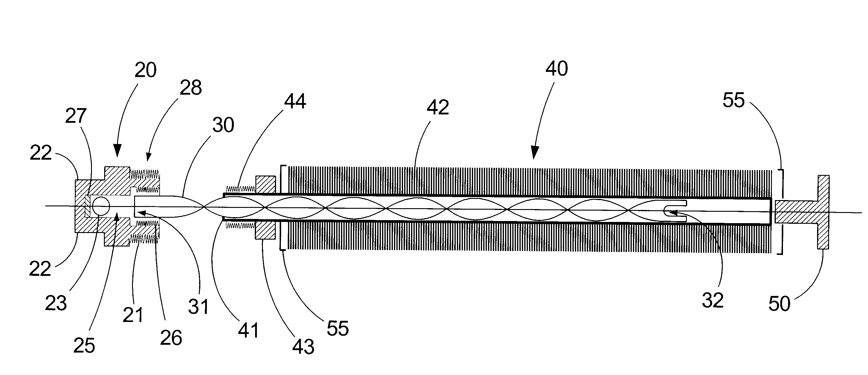
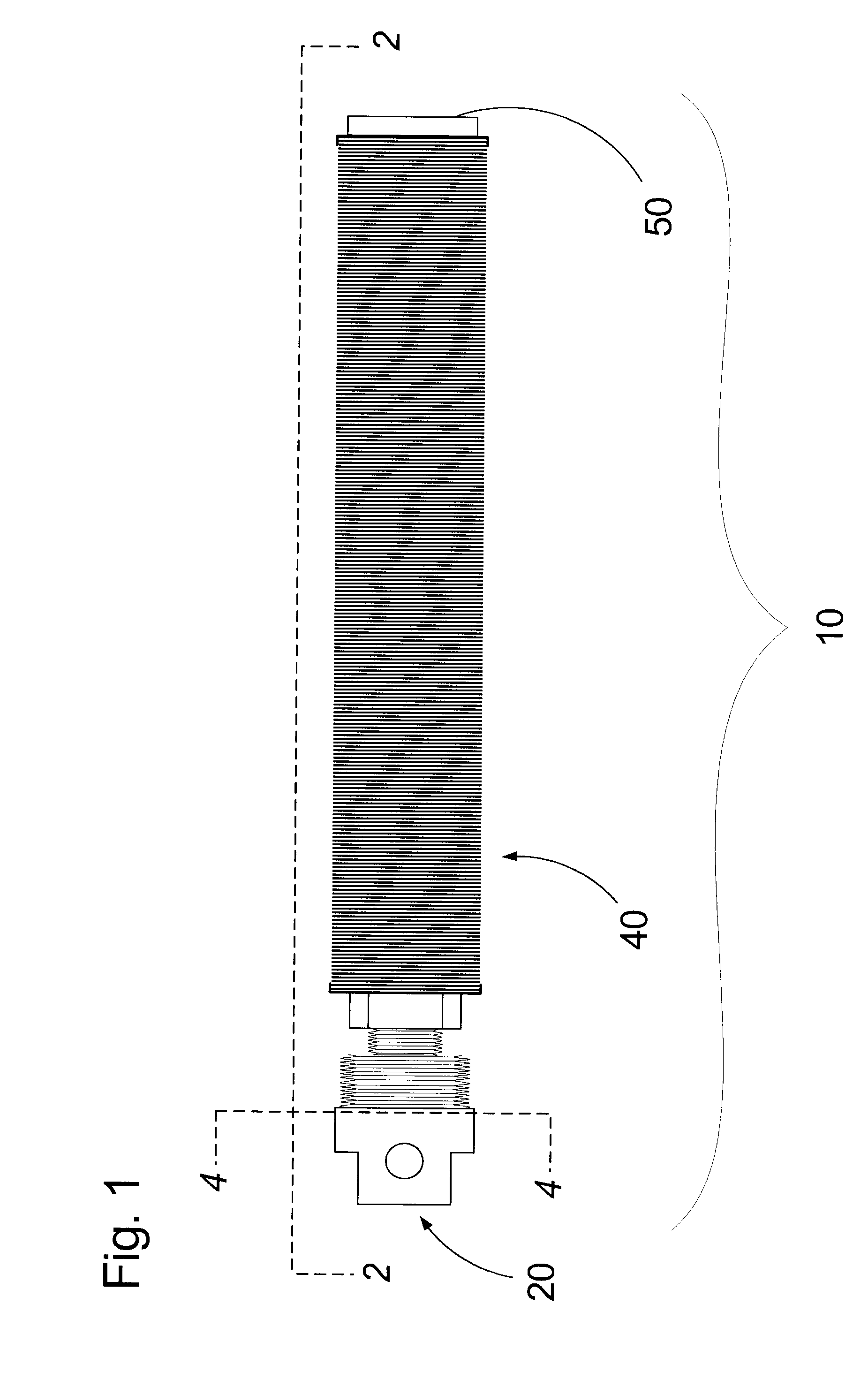
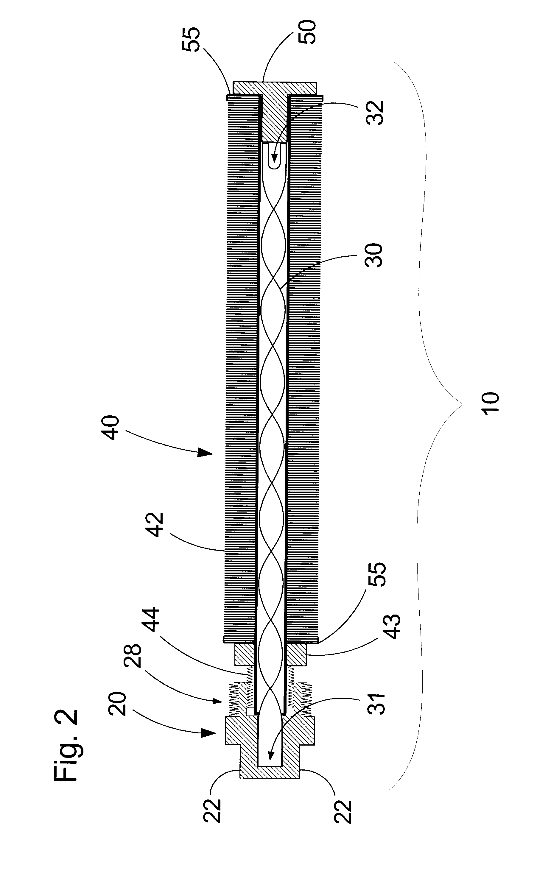
[0028]An exemplary embodiment of the turbulated submersible heat-exchange apparatus of the present invention is shown in the accompanying FIGS. 1-4, and is generally referred to by the numeral 10. The apparatus 10 comprises an elongate cylindrical heat-exchanging component 40 interconnected at one end with a coupling manifold 20 while the other end of component 40 is sealably engaged with a plug 50. A spiralled turbulator insert 30 extends through the heat-exchanging component 40 and abuts the manifold 20 and plug 50.

[0029]The coupling manifold 20 is provided with a collar 28 having an outward-facing male-threaded coupling portion 21 configured for threadably and sealably engaging a tank housing (not shown) and an inner-facing female-threaded coupling portion 26 for sealably interconnecting with the heat-exchanging component 40. A bore 25 extends through the collar 28 into the body of the coupling manifold 20 and communicates with a threaded inlet / outet port 23 and a threaded inlet / ...


PUM


Abstract

A submersible heat-exchanging apparatus comprises a cylindrical heat-exchange component configured with one end for sealingly engaging a terminal plug and the other end for sealingly engaging and communicating with a coupling manifold having opposed inflow and outflow ports. A flow-directing elongate insert is provided with one end configured to engage the coupling manifold interposed the inflow and outflow ports, and the other end provided with an aperture and configured for abutting the terminal plug. The flow-directing elongate insert is configured to slidingly contact and cooperate with the inner walls of the heat-conductive conduit thereby partitioning the heat-conductive conduit into two opposed fluid transmission channels wherein one channel communicates with the inlet port and the other channel communicates with the outlet port. The coupling manifold is configured to sealingly engage an aperature provided therefore in a fluid-containing receptacle whereby the heat-exchange component extends into the receptacle.

Description

FIELD OF THE INVENTION[0001]This invention relates to heat exchangers. More particularly, this invention relates to submersible heat exchangers configured for heating and / or cooling fluids contained in tanks.BACKGROUND OF THE INVENTION[0002]Heavy-duty transportation and construction equipment are typically powered by diesel-fuelled engines. Such equipment are commonly adapted with operator-controlled task-performing attachments that are precisely manipulated by hydraulic cylinders in cooperation with hydraulic oil pumps. The viscosities of diesel and hydraulic oils increase significantly as ambient temperatures decrease e.g., during extended cold periods and during winter months in temperate and in far northern and southern geographies. As ambient temperatures progressively drop below freezing (i.e., 0° C.), diesel and hydraulic oils continue to thicken to the point of forming gels and / or waxes. Cold weather conditions impede the transmission of thickened diesel fuel oils from their...

Claims


Application Information

Patent Timeline
Patent Type & Authority Applications(United States)
IPC IPC(8): F28F9/02F28F1/10F28F1/36F15B21/042
CPCF02M31/16F02M37/0082F15B21/042F28D1/0213F28D7/12F28F1/24F28F9/00F28F9/0246F28F13/12F28F2220/00Y02T10/126F28F2009/222F28F1/40Y02T10/12
Inventor ARNOT, ROGER
Owner ARNOT ROGER
Why Eureka
Try Eureka