Heat converter for heating automobile

A technology for heat exchangers and automobiles, applied in heat exchange equipment, heat exchanger types, heat exchanger shells, etc., can solve problems such as leakage, reduce heater efficiency, lack of sealing, etc., to achieve pressure-resistant liquid-tight, firm brazing The effect of easy connection and manufacturing process

Inactive Publication Date: 2010-06-16
BEHR GMBH & CO KG
View PDF6 Cites 2 Cited by
  • Summary
  • Abstract
  • Description
  • Claims
  • Application Information

AI Technical Summary

Problems solved by technology

[0005] When the principle of multiple baffles in cross convection is implemented on modern heaters as described in the documents provided by the applicant mentioned above, especially when two or more longitudinal partitions are arranged in the collecting tank And when it is sealed and brazed with the tube, tube sheet and header box wall, it will cause many problems
It is also to be taken into account that the chambers divided by longitudinal partitions are not completely sealed against each other, so that leakage can occur
Especially in the case of low volume flows of coolant, this will reduce the efficiency of the heater

Method used


Image

  • Heat converter for heating automobile
  • Heat converter for heating automobile
  • Heat converter for heating automobile

Examples


Embodiment Construction

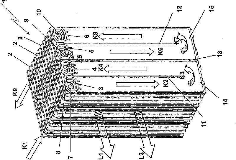
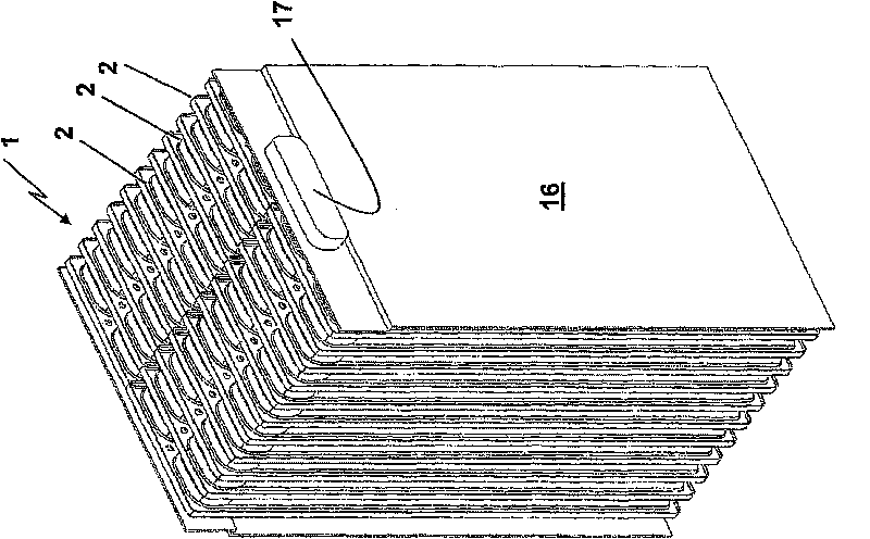
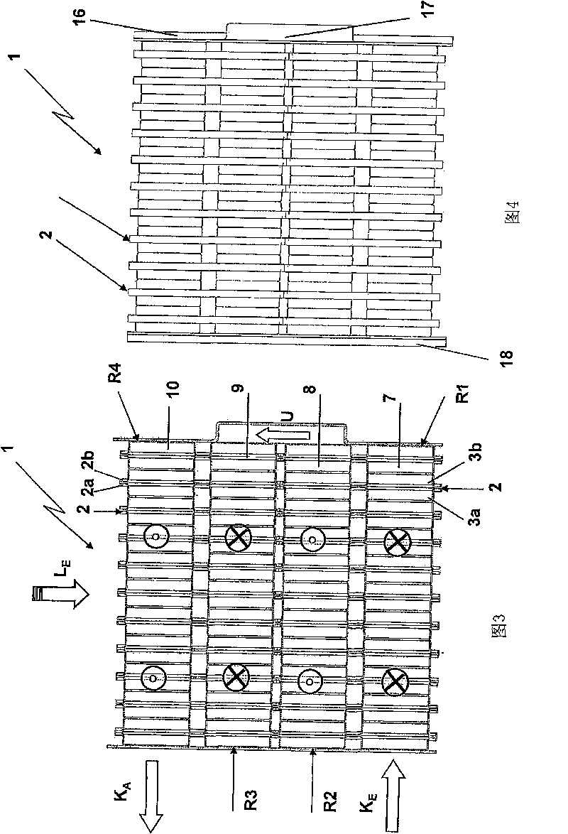
[0032] figure 1 Among them is a heater 1 according to the present invention with a plate structure, that is, the heater 1 is composed of a plurality of plates 2, which form a flow channel for the heat-carrying fluid, preferably coolant, in the cooling circuit of the automotive internal combustion engine. The plate 2 has dish-shaped openings 3 , 4 , 5 , 6 in its upper region, which together with adjacent dish-shaped openings (also referred to simply as dishes 3 , 4 , 5 , 6 ) form collecting ducts 7 , 8 , 9, 10. The term "collecting pipe" used here only also includes the concept of "distributing pipe". Furthermore, the plate 2 has non-perforated partitions 11 , 12 and a centrally penetrated partition 13 . All the plates 2 are made of aluminum and are brazed together, as will be explained further below. The flow route of the coolant is schematically indicated by arrows K1 to K9 indicating flow. The non-penetrating partitions 11, 12 form baffle areas 14, 15 through which the c...


PUM


Abstract

The present invention relates to a heat converter (1) for heating an automobile. The heat converter has a plurality of flow passages, the first side of the flow passages is flowed through by a heat transport fluid, the second side is flowed and circulated by air, wherein, the heat transport fluid and the air current are intersect and form a converted circulation, and the heat transport fluid flows and turns back at least two times in an in opposite direction of the flowing of air. The present invention is characterized in that a flow passage is made of a set of sheets (2), wherein, each sheet (2) has two half-sheets (2a, 2b) and at least three flow paths that can be flowed through.

Description

technical field [0001] The invention relates to a heat exchanger for automobile heating. Background technique [0002] Heat exchangers for vehicle heating, also known as space heaters or radiators, are today usually brazed all-metal heat exchangers. The known heater has a heater core, also referred to as core, which consists of tubes and fins, preferably flat tubes and corrugated fins. The tubes run into the header tank and are brazed to the bottom of the header tank. The heated coolant from the cooling circuit of the internal combustion engine passes through the tubes in the heater. The fins in the core are circulated by the surrounding air, which absorbs heat from the coolant and conveys it into the passenger compartment. The first requirement of the heater is to achieve as uniform a temperature distribution as possible on the air outlet side over the entire air outlet plane, ie in height and width direction. [0003] In DE 197 52 139 A1, the applicant proposes that th...

Claims


Application Information

Patent Timeline
IPC IPC(8): F28D1/03F28F3/08F28F9/00
CPCF28D1/0341
Inventor 米夏埃尔·科尔托马斯·施特劳斯
Owner BEHR GMBH & CO KG
Why Eureka
Try Eureka