Conduit connector

a technology of conduit connectors and connectors, which is applied in the direction of coupling device connections, manufacturing tools, engagement/disengagement of coupling parts, etc., can solve the problems of increasing the cost of installing electrical systems, increasing the cost of electrical systems, and expensive installation of electrical systems

Active Publication Date: 2009-09-03
SIGMA ELECTRIC MFG
View PDF33 Cites 22 Cited by
  • Summary
  • Abstract
  • Description
  • Claims
  • Application Information

AI Technical Summary

Problems solved by technology

The installation of electrical systems is generally expensive as an electrician must first install the enclosures, route conduit between each enclosure, and install connectors and then pull all necessary electrical wiring through the conduit.
In other words, installation is expensive because it is labor intensive.
Locknut connectors increase the cost of installing electrical systems for a number of reasons.
The current art two-part locknut connectors are plagued with labor intensive problems.
Consequently, it is difficult to hold a tool or a piece of conduit while reassembling the connector.
These situations, while rare, raise serious safety issues.
Those persons skilled in the art know that finger tightened two-part locknut connectors can eventually loosen, and a loose connector can cause great strain to be put onto the electrical wires and their connections resulting in an increase in the probability of an electrical fire or other electrical problems, such as poor grounding.
Secondly, when the electrician disassembles the fitting by taking the locknut off the connector, the locknut can be dropped or misplaced.
If the locknut cannot be found, the connector is useless.
A third common problem with the present locknut connectors is the locknut is easily cross threaded onto the male thread.
On occasion, cross threading the locknut will damage the male threads on the connector making it difficult or impossible to reuse the connector.
A fourth problem with the present two-part locknut connectors is the distance the male end protrudes into the junction box.
The space limitation becomes an acute problem when an additional connector is installed.
The male threaded end protrudes well past the depth of the locknut and may interfere with another connector, the contents of the enclosure, or wiring inside the box.
Typically, the electrician may clip off some of the receptacle or mounting screws, or completes a combination of space enlarging modifications, all of which prolong installation time and threaten the integrity of the system as designed.
A fifth common problem with the present two-part locknut connectors occurs during disassembly of the connector from the enclosure.
The disassembly of the locknut connector is more time consuming than the installation.
Similar to the installation, if the threads are damaged during disassembly, the connector is useless.
Also similar to the installation problems, if the locknut is lost, it must be replaced if the connector is to be used again.
The snap-in connector presents similar problems.
However, the most significant problem is that these connectors, in most cases, do not create a rigid connection.
The loose fit may cause electrical continuity problems, a highly dangerous situation, since the box, the conduit, and the connector are intended to be part of the electrical grounding system in some applications.
Additionally, there remains an unfulfilled need to provide a generally universal connector providing a rigid; and where required by code, an electrically conductive connection; and conserves space within the enclosure.

Method used


Image

  • Conduit connector
  • Conduit connector
  • Conduit connector

Examples


Embodiment Construction

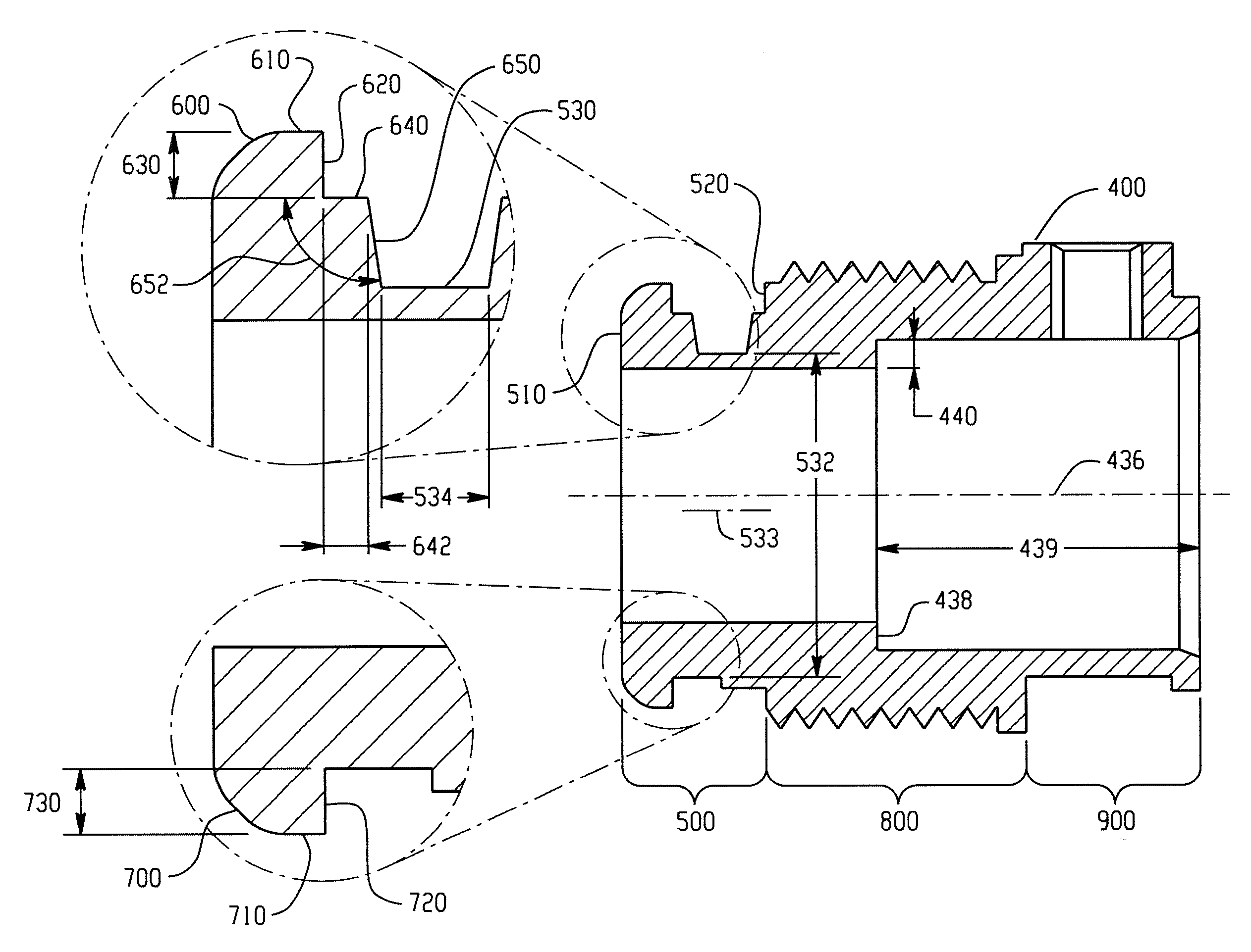
[0037]A conduit connector is designed to quickly, safely, and rigidly connect to a junction box to facilitate the connection of a conduit to cables (and other electrical conductors) and to a wide variety of boxes (e.g., junction boxes, and so forth). Therefore, as used in this specification, the term conduit is not limited to standard rigid electrical conduit, but shall be intended to mean any type of conduit, any type of cable, or any other type of electrical conductor. The junction box is intended to include many types of electrical enclosures, such as, outlet and fixture boxes, enclosures for disconnect switches and motor starters, and transformer enclosures. The junction box can be made from steel, plastic, or other commercially feasible and acceptable materials.

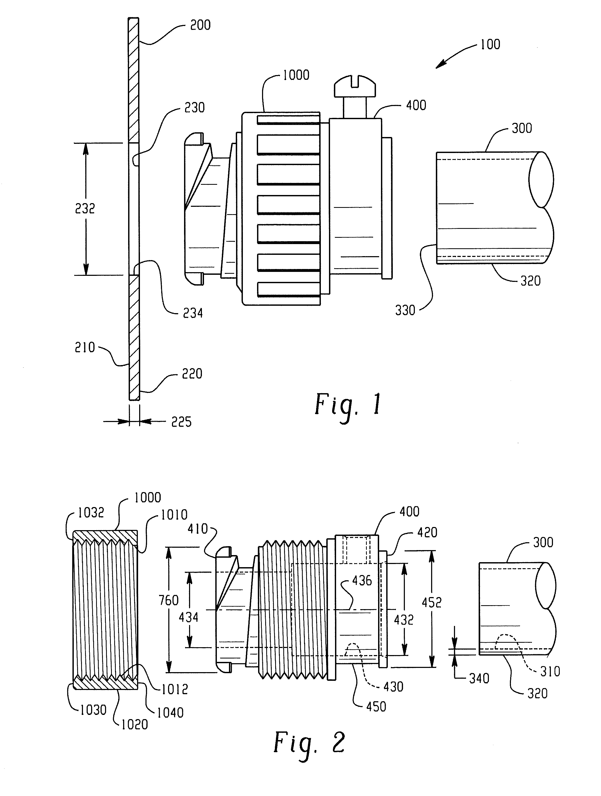
[0038]Referring to FIG. 1, the junction box (200) has a box interior surface (210), a box exterior surface (220), and a box thickness (225). Typically, the junction box (200) has a plurality of prefabricated holes or ope...


PUM

PropertyMeasurementUnit
flank angleaaaaaaaaaa

Abstract

In an embodiment, a conduit connector can comprise: a body comprising a box engagement region capable of engaging an opening in an enclosure and a spring configured to engage the connector and the enclosure. The box engagement region can have a root surface, a leading tab, and a follower tab wherein the root surface and leading tab can be located between a leading edge and a secondary edge. A leading tab perimeter edge and a follower tab perimeter edge define a tab perimeter diameter that is larger than an opening in the enclosure. When the leading tab is inserted into the enclosure the spring can be disposed to engage the secondary edge and the enclosure.

Description

CROSS REFERENCE TO RELATED APPLICATIONS[0001]This application claims priority to U.S. Provisional Application Ser. No. 61 / 067,553, filed Feb. 29, 2008 and to U.S. Provisional Application Ser. No. 61 / 069,156, filed Mar. 13, 2008, both of which are incorporated herein in their entirety.TECHNICAL FIELD[0002]The instant application relates to adapters for connecting electrical conduit to junction boxes, outlet boxes, or other enclosures, and, more particularly, to an electrical conduit connector with a body, and a spring.BACKGROUND[0003]The most common use for electrical conduit connectors is to facilitate the connection of a conduit or cable to a junction box. The junction box can be a variety of electrical enclosures such as an outlet box, transformer enclosure, circuit panel, lighting fixture—the list is nearly endless. Similarly, the conduit can be rigid or flexible, or could be hose, other tubing capable of routing electrical wire, or cable. Cable can be non-metallic sheathed cable...

Claims


Application Information

Patent Timeline
Patent Type & Authority Applications(United States)
IPC IPC(8): H02G3/14B23P11/00
CPCY10T29/49826H02G3/0625
Inventor SHEEHAN, ROBERT K.CHAVAN, VINAYAK MANOHAR
Owner SIGMA ELECTRIC MFG
Why Eureka
Try Eureka