
Ultraviolet treatment device

a treatment device and ultraviolet technology, applied in the field of ultraviolet treatment devices, can solve the problems of affecting the health of patients, affecting the quality of life of patients, and affecting the effectiveness of hand washing policies and regular keyboard cleaning policies,

Active Publication Date: 2009-09-03
VIOGUARD CORP
View PDF18 Cites 75 Cited by
  • Summary
  • Abstract
  • Description
  • Claims
  • Application Information

AI Technical Summary

Benefits of technology

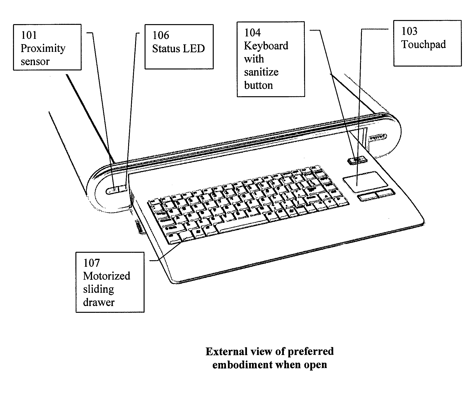
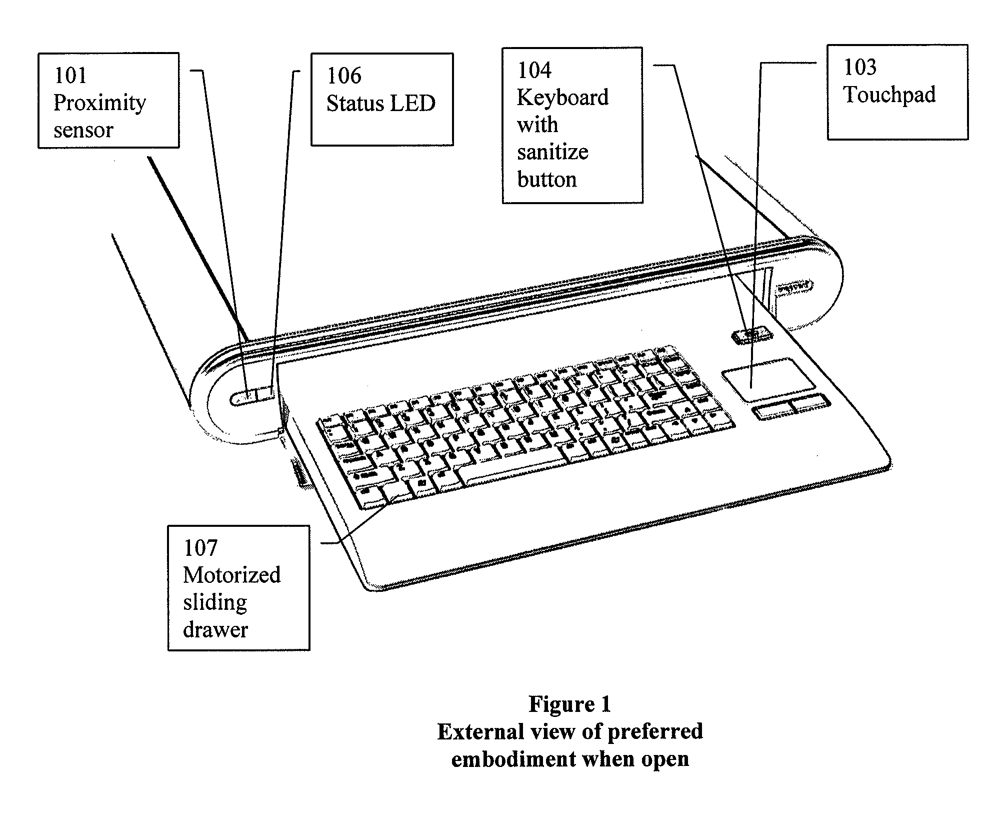
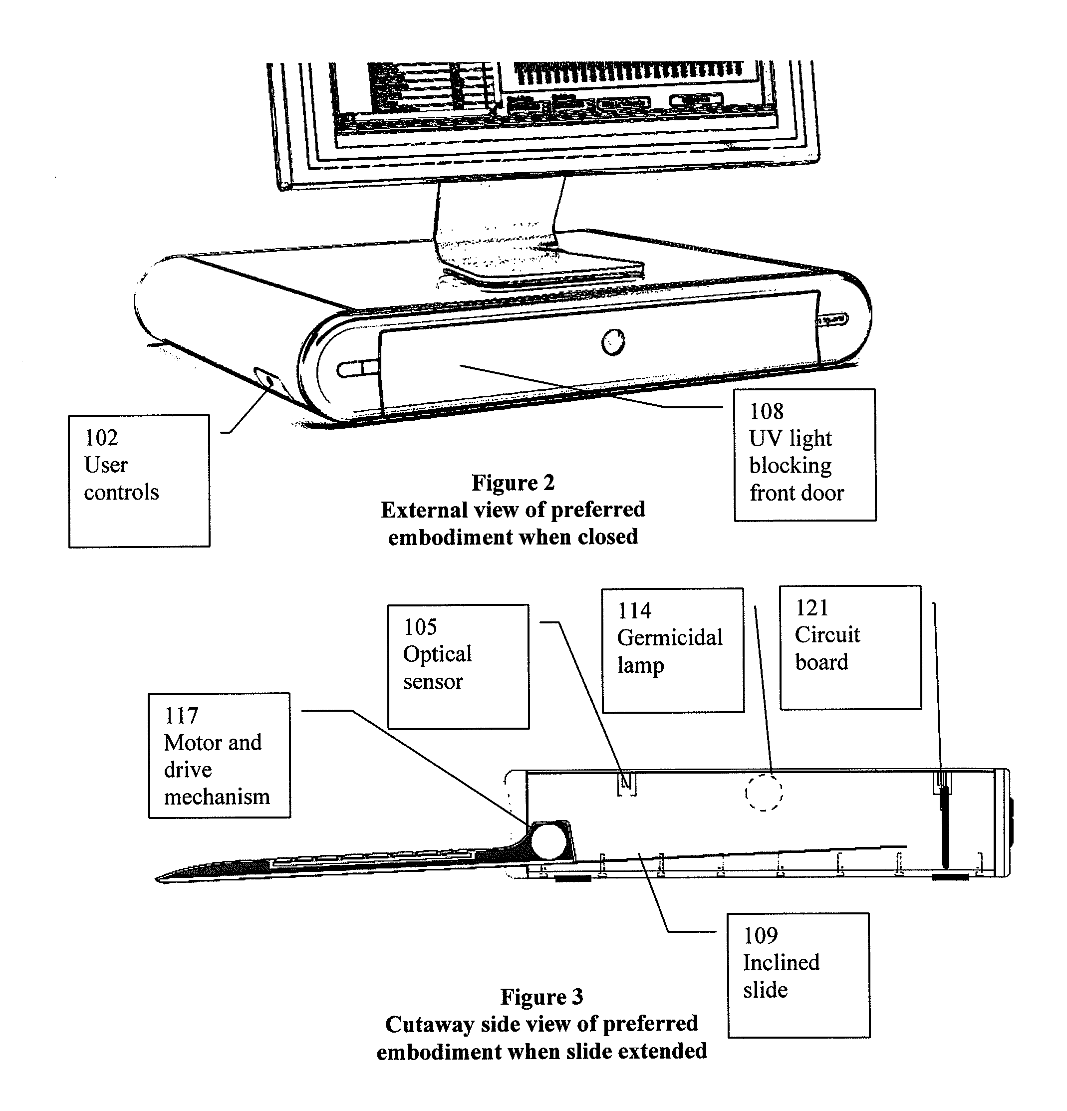
"The invention is a light tight box with a motorized drawer and door that can be opened to use the touchpad and keyboard. It closes to form an ultraviolet light-tight enclosure for rapid sanitizing cycles. The sanitizing cycle can be activated by an infrared proximity sensor, waving a hand near the sensor, or touching a special key on the keyboard. The device can also be controlled programmatically by an attached PC and control software. The sanitizer includes a controller and light sensor to measure the intensity of light emitted by the UV source and determine the duration of exposure required to achieve a target total UV energy dosage. The inclined slide provides mechanical stability during use."

Problems solved by technology

Healthcare acquired infections such as MRSA (Methicillin Resistant Staphylococcus Aureus) cause tens of thousands of deaths each year in the US alone, cost the economy billions through extended hospital stays and wrongful death lawsuits, and contribute to rising medical costs worldwide.
Hand washing policies and regular keyboard cleaning policies have had limited effectiveness in practice since they must take place before every use to eliminate any possibility of patient to patient contamination through the hands of a healthcare worker.
Large medical facilities with hundreds or thousands of computer keyboards and mice have deemed it impractical to manually sanitize them with disinfectant more than once or twice per day, even though they may be used by dozens of contaminated employees in between cleanings.
However, the output of commonly available UV lamps drops significantly over time, and is also affected by voltage, current, manufacturing differences between lamps, and accumulation of dust and other contaminants on the bulb.
Others have tried to construct UV sanitation enclosures, with limited success.

Method used


Image

  • Ultraviolet treatment device
  • Ultraviolet treatment device
  • Ultraviolet treatment device

Examples


Embodiment Construction

[0018]One example of the invention includes a method to determine total required exposure time by either directly measuring the UV-C output at 253.7 nm or indirectly by measuring the intensity of one or more spurious spectral lines of the lamp in the visible region of approximately 380-750 nm as a proxy for the UV lamp output, and then calculating the exposure duration and terminating the exposure when the desired total energy has been reached. Direct measurement of the UV-C light can be accomplished with a sensor such as a silicon-carbide photodiode. However, such devices are expensive and so not desirable for inclusion in a high volume production device.

[0019]In the case of indirect measurement of UV emissions, a low cost visible or even wide spectrum infrared sensor can be used. The relative amplitudes of spurious visible spectral lines emitted by a UV source and their ratio to the primary UV output can be determined in advance for a particular source. Thus, knowledge of the lamp...


PUM

PropertyMeasurementUnit
wavelength regionaaaaaaaaaa
field of viewaaaaaaaaaa
movementaaaaaaaaaa

Abstract

A keyboard and touchpad or mouse UV treatment system with optical sensor and inclined slide is described. A proximity sensor, microcontroller firmware, and motorized mechanism allow activation of the sanitization cycle by personnel with contaminated hands without risk of additional spreading of pathogens to other personnel and patients. The inclined slide provides stability when operated on a desk, and the microcontroller and optical sensor determine the proper exposure time to compensate for lamp aging and variations in lamp output.

Description

PRIORITY CLAIM[0001]This invention claims the benefit of prior provisional application Ser. No. 61 / 033,270 filed on Mar. 3, 2008 and provisional application Ser. No. 61 / 098510 filed on Sep. 19, 2008.BACKGROUND OF THE INVENTION[0002]With increasing numbers of hospitals, clinics, and dental offices moving to fully computerized patient record systems, the number of computer keyboards and mice in these facilities has been steadily increasing. Keyboards and mice contaminated with pathogens have been identified as one of the leading vectors for transmission of infections and viruses from patient to patient in hospitals and clinics. Healthcare acquired infections such as MRSA (Methicillin Resistant Staphylococcus Aureus) cause tens of thousands of deaths each year in the US alone, cost the economy billions through extended hospital stays and wrongful death lawsuits, and contribute to rising medical costs worldwide. A significant percentage of patient to patient transmission of pathogens ca...

Claims


Application Information

Patent Timeline
Patent Type & Authority Applications(United States)
IPC IPC(8): G01N23/00G01J3/10
CPCA61L2/10A61L2202/14A61L2202/121A61L2/24
Inventor RANTA, CRAIGFISHER, STEVEN
Owner VIOGUARD CORP
Learn More