Method for repair of rail wheels and repaired article

a rail wheel and repair method technology, applied in the field of rail wheels, can solve the problems of no good repair techniques for rail wheels, no good rail wheel repair techniques, and inconvenient welding of a new ring to the wheel hub,

Inactive Publication Date: 2009-09-03
GENERAL ELECTRIC CO +1
View PDF8 Cites 26 Cited by
  • Summary
  • Abstract
  • Description
  • Claims
  • Application Information

AI Technical Summary

Problems solved by technology

Weld build-up or fusion welding of a new ring to the wheel hub is prohibitive because of tight quality standards imposed on rail wheels by the Association of American Railroads (AAR).
Currently there are no good repair techniques for rail wheels due to restrictions on inclusions or cracks that would generally result from traditional welding techniques.
However, a disadvantage to this approach is that the ring or “tire” is under tension in service, and as it wears thinner it becomes highly vulnerable to cracking.
Wheels are a high-cost item for rail operators.

Method used


Image

  • Method for repair of rail wheels and repaired article
  • Method for repair of rail wheels and repaired article
  • Method for repair of rail wheels and repaired article

Examples


Embodiment Construction

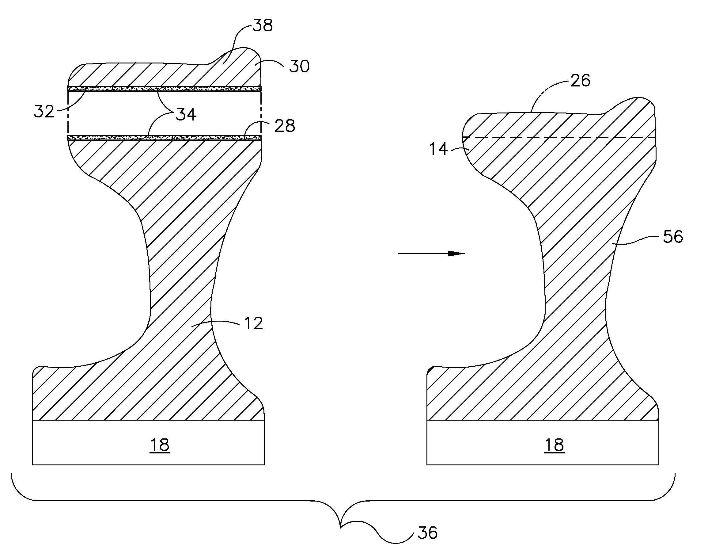
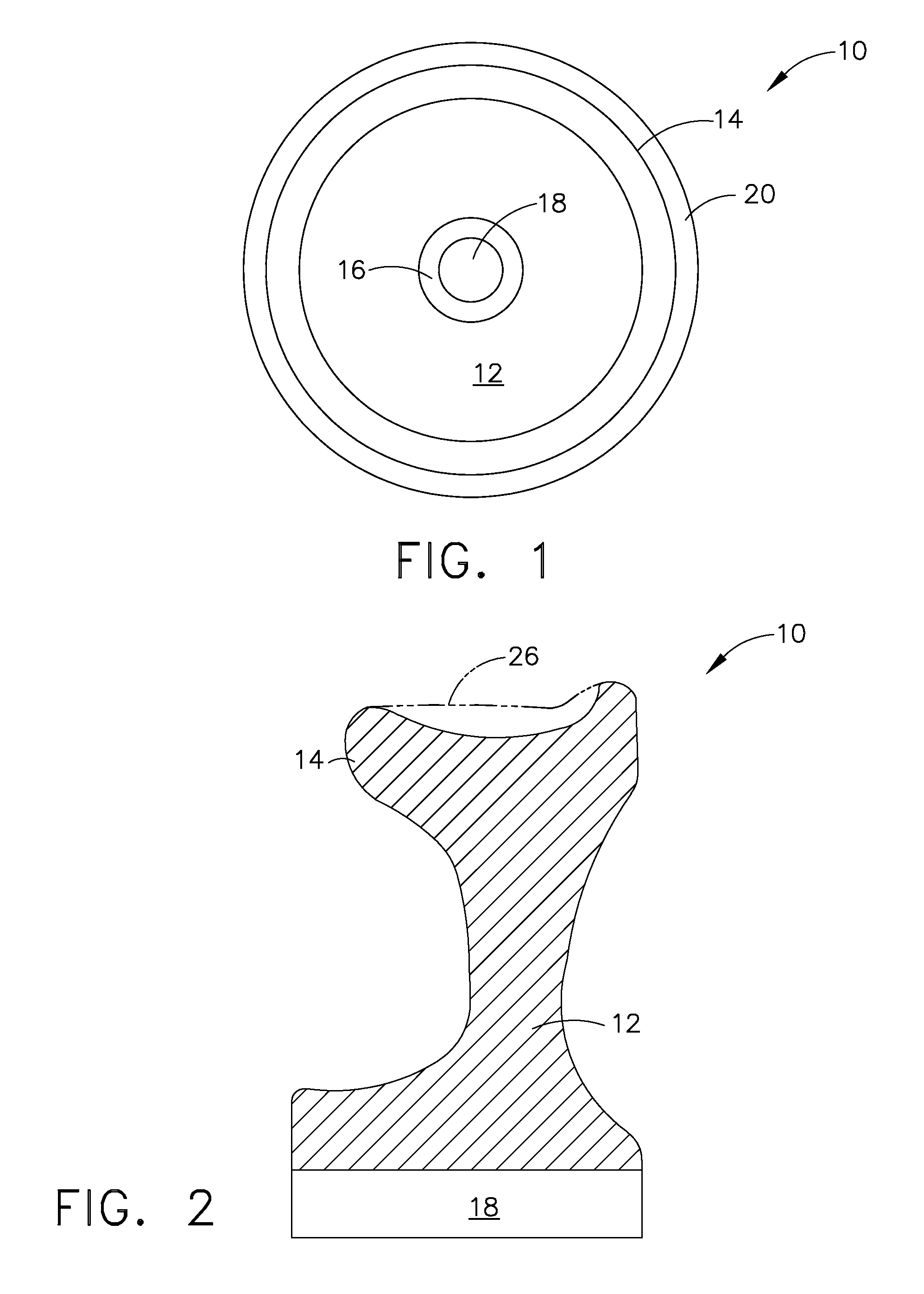
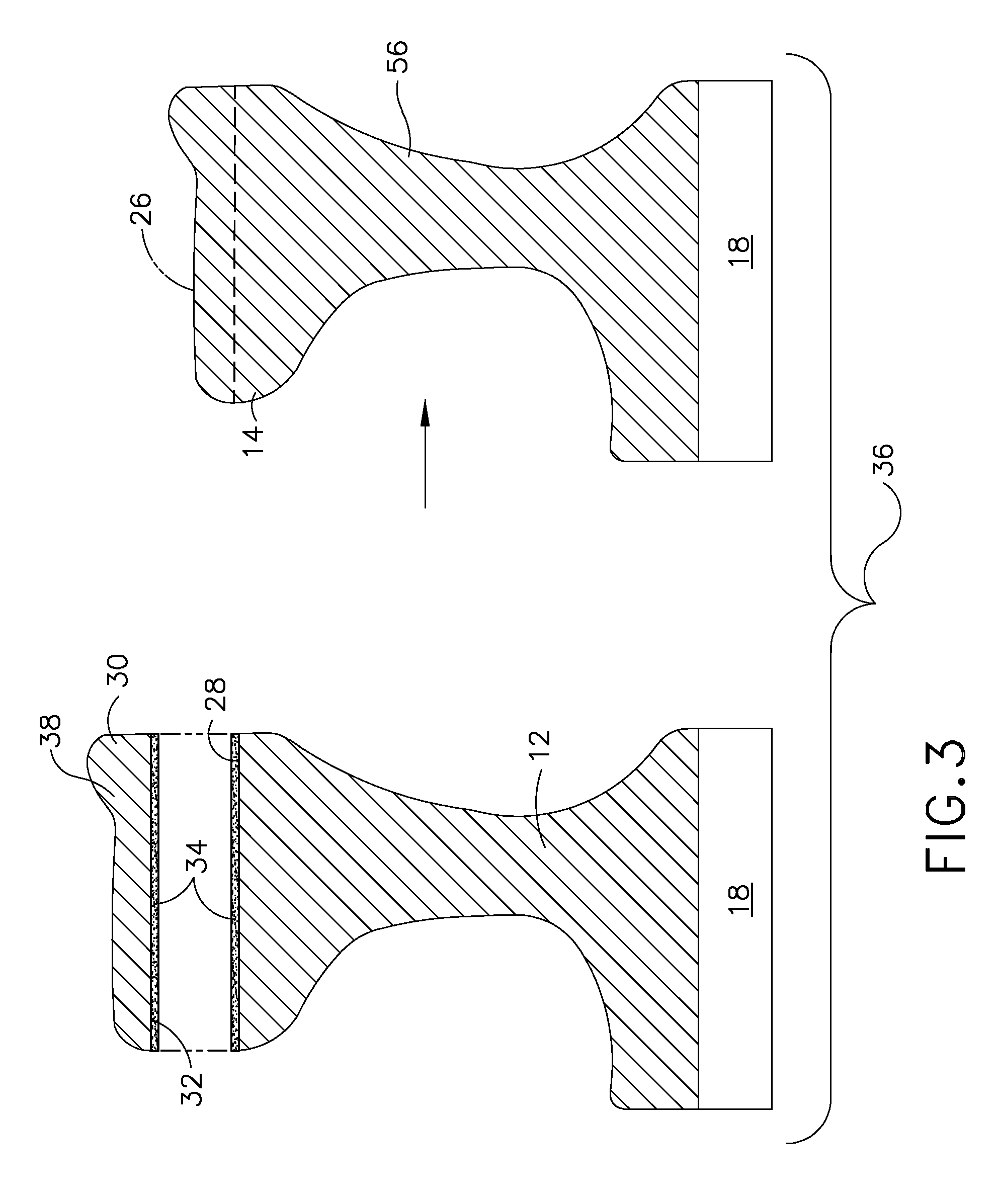
[0017]Referring to the drawings wherein identical reference numerals denote the same elements throughout the various views, FIG. 1 illustrates an exemplary railroad wheel 10 including a body 12 with a rim 14 extending about the circumference of the body. The body 12 has a hub 16 having a bore 18 therethrough for receiving an axle. In use, wheels are secured to opposing ends of an axle with the wheels spaced to rotatably contact parallel railroad tracks. A flange 20 extends radially outward from the rim for retaining the wheels on the railroad tracks. Railroad wheel 10 represents a wheel that has been used in service, and which exhibits wear or other defect(s).

[0018]As used herein, “wheel body” refers to that portion of railroad wheel 10 that is utilized in an exemplary repair process.

[0019]As used herein, “faying surface” means that surface of a member which is in contact with, or in close proximity to, another member to which it is to be joined.

[0020]As used herein, “diffusion bond...


PUM

PropertyMeasurementUnit
bonding temperaturesaaaaaaaaaa
bonding pressureaaaaaaaaaa
metallurgically compatibleaaaaaaaaaa

Abstract

A method includes shrink fitting a ring member about a railroad wheel body and metallurically bonding the ring member to the railroad wheel body. A wheel assembly includes an inner portion obtained from a worn railroad wheel, a ring member disposed about the inner portion, and suitable electroplating material disposed on at least one of the faying surfaces. The wheel assembly may be heated under suitable conditions to provide diffusion bonding across interfacing faying surfaces to produce an integral wheel structure. Appropriate quenching, tempering, and finishing processes may be utilized to obtain desired properties. An article formed thereby includes an inner body portion obtained from a worn railroad wheel and a metallurically bonded outer circumferential portion. The outer portion may comprise a composition selected for desired wear characteristics.

Description

BACKGROUND OF THE INVENTION[0001]This invention relates generally to a railroad wheels, and more specifically to a method to repair worn railroad wheels to enable them to be returned to service.[0002]During service, railroad wheels wear away, as they are designed to be sacrificial relative to the railroad tracks. Additionally, wheels can be removed for other defects such as spalling, shelling, and out-of-roundness.[0003]When a wheel is removed from service for tread defects, it may be re-machined to adjust its profile relative to the rail geometry, provided that there is sufficient rim metal remaining. Presently, the most common reason that wheels are discarded is because of wearing to a minimum dimension.[0004]Weld build-up or fusion welding of a new ring to the wheel hub is prohibitive because of tight quality standards imposed on rail wheels by the Association of American Railroads (AAR). Currently there are no good repair techniques for rail wheels due to restrictions on inclusi...

Claims


Application Information

Patent Timeline
Patent Type & Authority Applications(United States)
IPC IPC(8): B60B17/00B23P11/02B23P6/00
CPCB23P6/00Y10T29/49726B60B17/0068Y10T29/49885Y10T29/49723Y10T29/49865Y10T29/49968Y10T29/49728Y10T29/49742Y10T29/49725Y10T29/49483Y10T29/49732Y10T29/49734Y10T29/49737Y10T29/49771Y10T29/49485B60B17/0006
Inventor MANTKOWSKI, THOMAS EDWARD
Owner GENERAL ELECTRIC CO
Why Eureka
Try Eureka