
Downhole micro magnetic resonance analyzer

a micro-magnetic resonance analyzer and analyzer technology, applied in the field of small-scale downhole nuclear magnetic resonance (nmr) tools, can solve problems such as the inability to perform nmr spectroscopy

Active Publication Date: 2009-09-03
SCHLUMBERGER TECH CORP
View PDF14 Cites 23 Cited by
  • Summary
  • Abstract
  • Description
  • Claims
  • Application Information

AI Technical Summary

Problems solved by technology

The static field of a downhole NMR tool is generally too inhomogeneous to allow NMR spectroscopy to be performed.

Method used


Image

  • Downhole micro magnetic resonance analyzer
  • Downhole micro magnetic resonance analyzer
  • Downhole micro magnetic resonance analyzer

Examples


Embodiment Construction

[0021]This invention relates to a lab-on-a-chip / micro magnetic resonance analyzer and method of using same. A micro magnetic resonance analyzer (micro MR analyzer) can measure nuclear spins or electron spins. One that measures nuclear spins is referred to as a micro NMR analyzer, and one that measures electron spins is referred to as a micro ESR analyzer. Although the discussion below is directed to a micro NMR analyzer, it is equally applicable to a micro ESR analyzer.

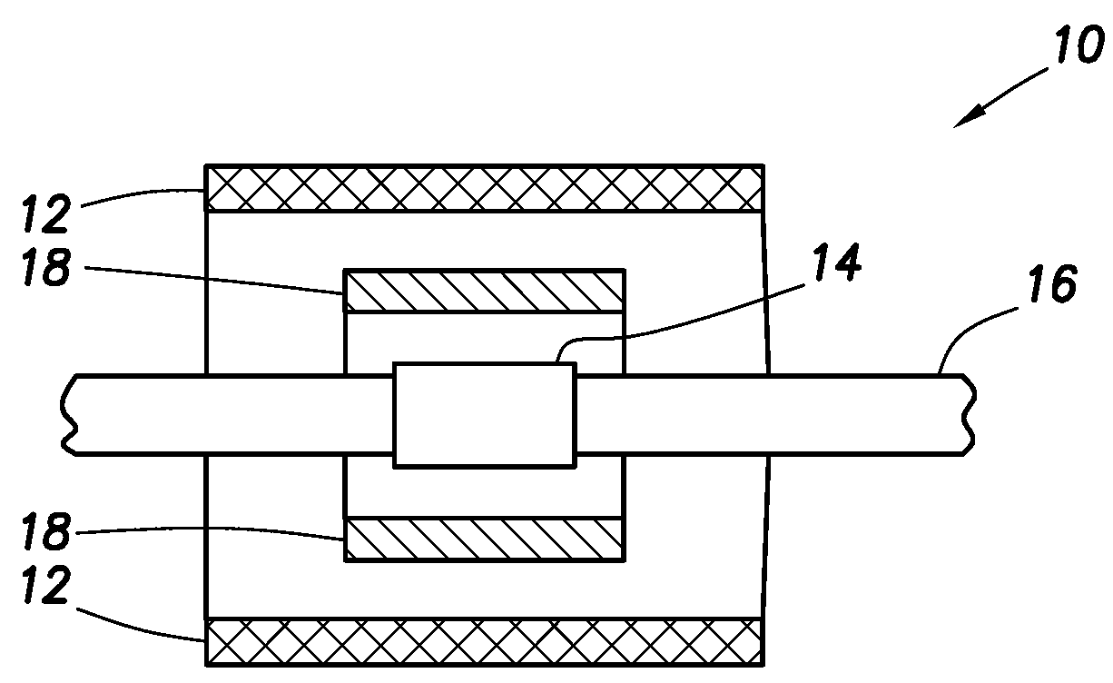
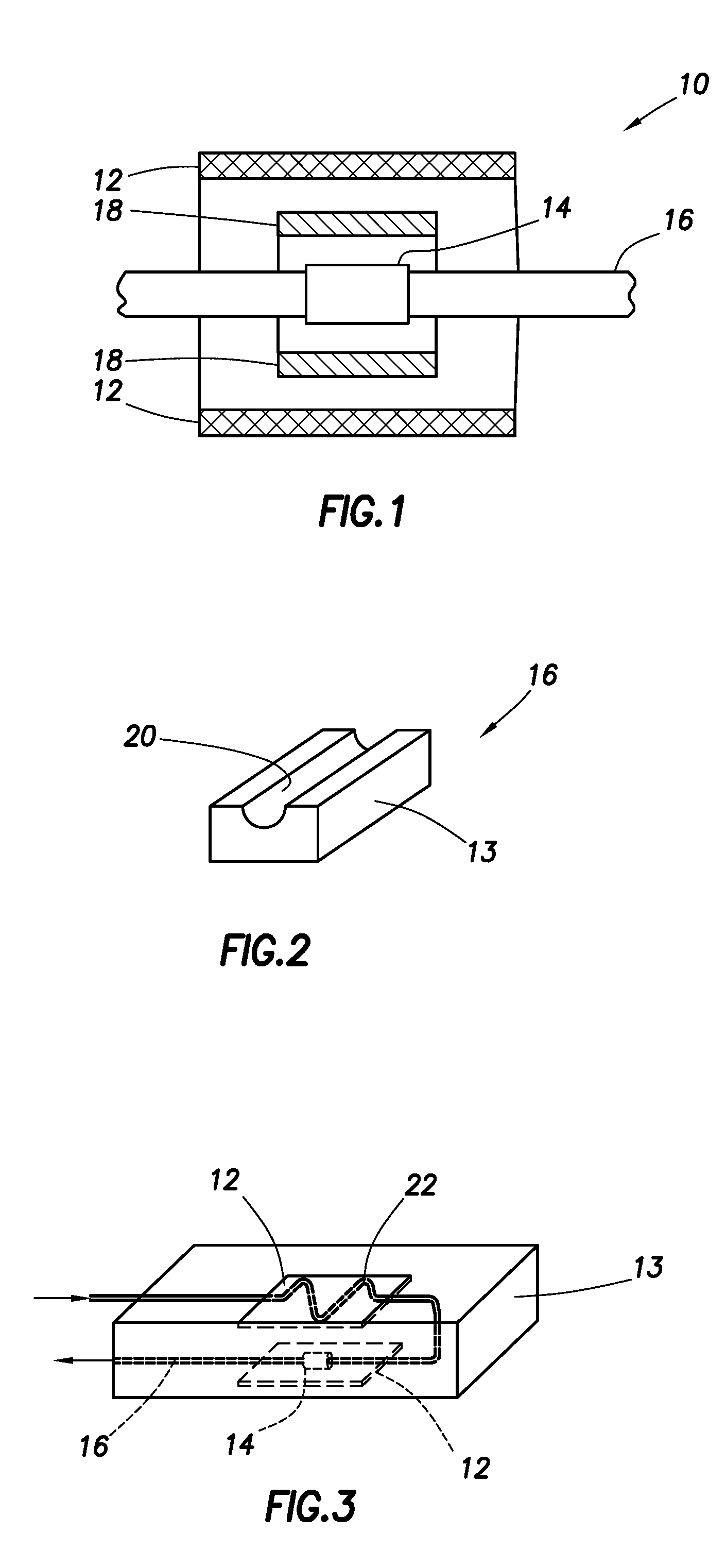
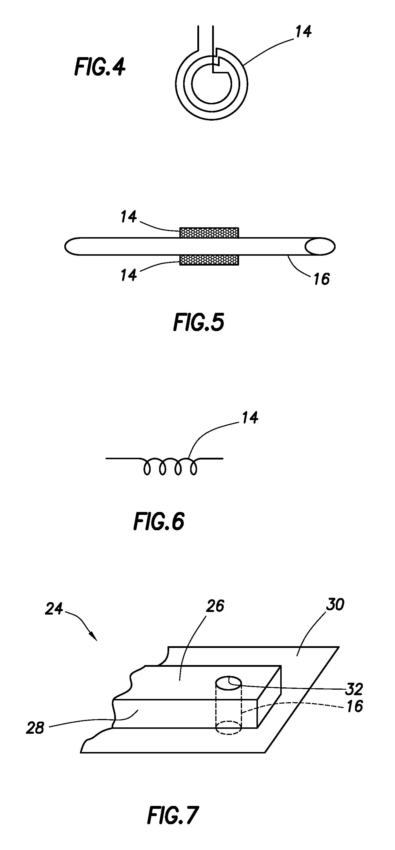
[0022]As shown in FIG. 1, the micro NMR analyzer 10 has a micro or macro sized magnet 12, a micro RF coil 14, a micro sample tube 16, and optionally a micro gradient coil 18. The micro RF coil antenna 14 (coil diameter 14 (or probe) is small, the NMR sensitive region is also small and the static magnetic field inhomogeneity will be small over this region. As a result, it is possible to make NMR measurements using the micro NMR analyzer 10 even though the static magnetic field is non-homogeneous when considered over la...


PUM


Abstract

A downhole micro MR analyzer for use in a wellbore, having a micro sample tube, a micro RF coil in close proximity to the micro sample tube, and one or more magnets disposed about the micro sample tube is disclosed. The micro MR analyzer can be used for nuclear magnetic resonance or electron spin resonance experiments to ascertain formation properties and chemical compositions.

Description

CROSS-REFERENCE TO RELATED APPLICATIONS[0001]This application claims priority to and the benefit of U.S. Provisional Application No. 60 / 746,303, filed May 3, 2006.BACKGROUND[0002]1. Field of Invention[0003]The present invention pertains to downhole nuclear magnetic resonance (NMR) tools for use in a wellbore, particularly small-scale downhole NMR tools.[0004]2. Related Art[0005]Downhole NMR tools are commonly used, in oil and gas exploration, for example, to ascertain or infer properties of the subsurface formations encountered by a wellbore. Downhole NMR tools may be used while drilling the wellbore, or may be run into the wellbore after drilling, for example, on a wireline. Various reservoir fluid properties can be measured using a downhole NMR tool. Measurements can be made on reservoir fluids in the formation, or measurements can be made on a fluid sample withdrawn from the formation or wellbore. The NMR tool can be a stand-alone tool or may be incorporated as a module in a flui...

Claims


Application Information

Patent Timeline
Patent Type & Authority Applications(United States)
IPC IPC(8): G01R33/44
CPCG01N24/081G01R33/302G01R33/3456G01R33/34061G01R33/34053G01R33/46G01R33/60G01V3/32
Inventor TAHERIAN, REZAGANESAN, KRISHNAMURTHYFREEDMAN, ROBERT
Owner SCHLUMBERGER TECH CORP
Learn More