Methods and Systems for Detecting Rotor Field Ground Faults In Rotating Machinery

a technology of rotating machinery and ground faults, applied in the direction of testing circuits, dynamo-electric converter control, instruments, etc., can solve problems such as short circuit between coil bars or turns, shorted turns, and ground condition

Inactive Publication Date: 2009-09-03
GENERAL ELECTRIC CO
View PDF5 Cites 29 Cited by
  • Summary
  • Abstract
  • Description
  • Claims
  • Application Information

AI Technical Summary

Benefits of technology

[0010]In accordance with one exemplary embodiment of the invention, a system for detecting abnormalities in a rotating machine is provided for. The system can include a rotor of the rotating machine comprising a plurality of field windings substantially disposed therein. The system can further include a stator of the rotating machine comprising a plurality of stator windings substantially disposed therein. An air gap exists between the rotor and the stator. The system can include a high-impedance grounding circuit at least temporarily connected between the rotor and a ground. Additionally, the system can include an air gap flux probe positioned at least temporarily between the rotor and the stator for measuring a magnetic flux density generated in the air gap during operation of the rotating machine. Finally, the system can further include an analyzer in electrical communication with the air gap flux probe for receiving an output of the air gap flux probe.
[...

Problems solved by technology

The insulation separating the coil bars and/or end turns occasionally may break down and cause short circuit between the coil bars or turns (also referred to herein as shorted turns).
These shorted turns may exist at standstill or may be caused as a result of the centrifugal force of the rotor under load.
Additionally, the coil components may cause the field windings to forge to the stator, causing a ground condition (also referred to herein as a ground fault).
These ground faults...

Method used


Image

  • Methods and Systems for Detecting Rotor Field Ground Faults In Rotating Machinery
  • Methods and Systems for Detecting Rotor Field Ground Faults In Rotating Machinery
  • Methods and Systems for Detecting Rotor Field Ground Faults In Rotating Machinery

Examples


Embodiment Construction

[0018]Embodiments of the invention now will be described more fully hereinafter with reference to the accompanying drawings, in which some, but not all embodiments are shown. Indeed, the invention may be embodied in many different forms and should not be construed as limited to the embodiments set forth herein; rather, these embodiments are provided so that this disclosure will satisfy applicable legal requirements. Like numbers refer to like elements throughout.

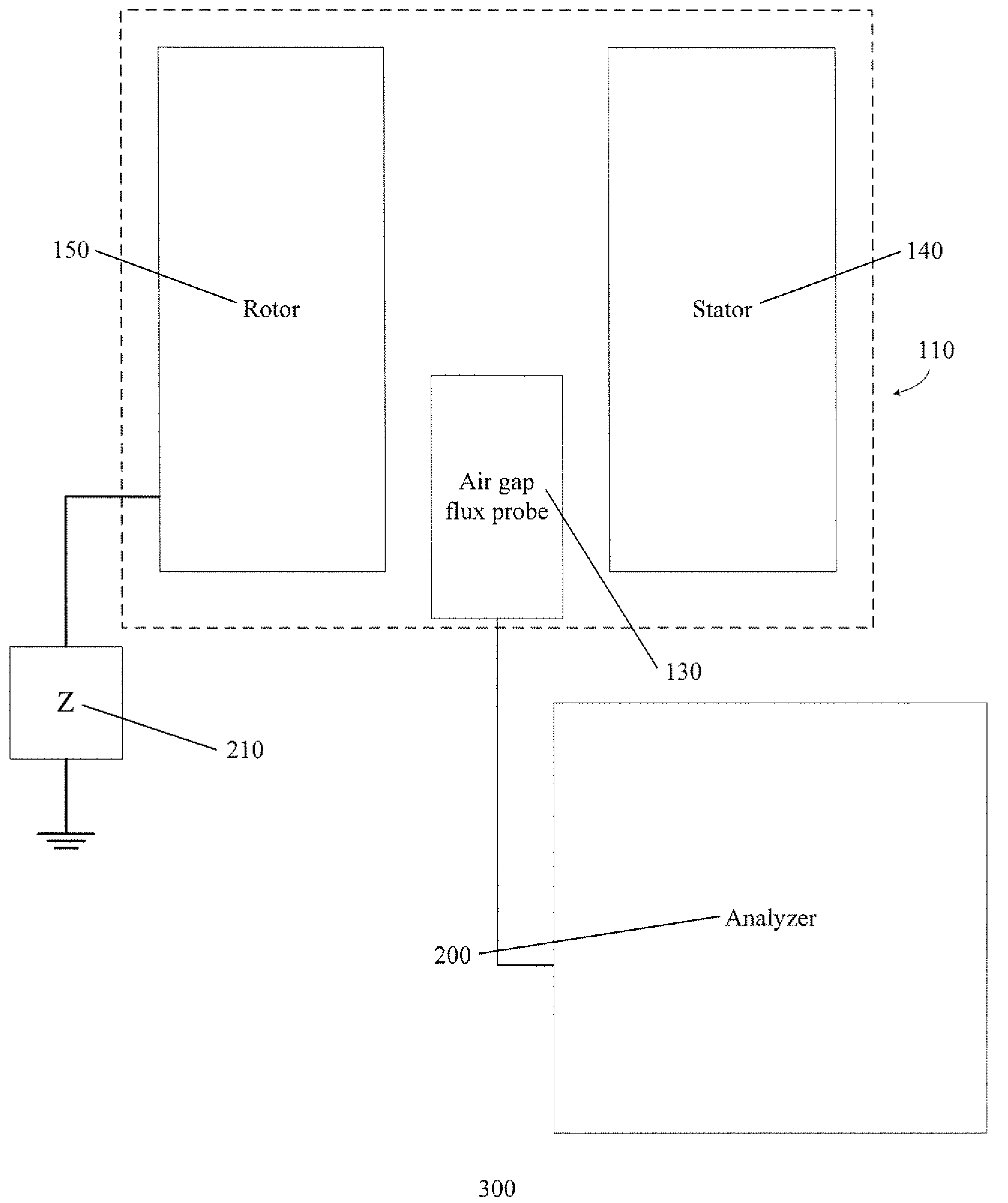
[0019]Methods and systems for detecting field ground faults in rotating machinery are provided for and described. Embodiments of such methods and systems provided can allow distinguishing ground faults from shorted turns in the rotor of the rotating machinery. At least some of embodiments of the methods and systems may include an air gap flux probe positioned in close proximity to the rotor and in between the rotor and stator of the rotating machinery. A high-impedance grounding circuit for applying a temporary ground across...


PUM


Abstract

Embodiments of the invention can include methods and systems for detecting rotor field ground faults in rotating machinery. In one embodiment, a system can include a rotor of the rotating machine comprising a plurality of field windings substantially disposed therein and a stator of the rotating machine comprising a plurality of stator windings substantially disposed therein, with an air gap existing between the rotor and the stator. The system can include a high-impedance grounding circuit at least temporarily connected between the rotor and a ground. Additionally, the system can include an air gap flux probe positioned at least temporarily between the rotor and the stator for measuring a magnetic flux density generated in the air gap during operation of the rotating machine. Finally, the system can further include an analyzer in electrical communication with the air gap flux probe for receiving an output of the air gap flux probe.

Description

TECHNICAL FIELD[0001]The invention relates generally to rotating machinery, and more specifically relates to methods and systems for detecting rotor field ground faults in rotating machinery.BACKGROUND OF THE INVENTION[0002]Rotating machinery, such as generators for converting mechanical energy to electrical energy, typically include a rotating component, the rotor, and a stationary component, the stator. The interaction of magnetic fields in the rotor and the stator is used to generate electric power.[0003]The high alternating current (AC) output power is conventionally generated in the stator operating as an armature. The rotor includes multiple field windings, which in conventional generators is generally an arrangement of conductive wires or bars in the rotor. The field windings in the rotor are generally an annular array of conductive coil bars or cables (collectively referred to herein as coil bars) arranged in slots around the outer periphery of the rotor. The coil bars gener...

Claims


Application Information

Patent Timeline
IPC IPC(8): G01R31/34G01R31/08
CPCG01R31/025H02K11/001G01R31/346G01R31/343G01R31/52H02K11/20G01R33/02H02H7/06H02P8/36
Inventor SALEM, SAMEH RAMADANSALON, SHEPPARDCHARI, MADABUSHI VENKATAKRISHNAMAKWON, O-MUN
Owner GENERAL ELECTRIC CO
Why Eureka
Try Eureka