Thermal printer

a printer and thermal technology, applied in the direction of power drive mechanism, printing, instruments, etc., can solve the problems of conventional mechanisms, inability to print high-speed, noisy matrix printers, etc., to facilitate the use of printers, and reduce the probability of damage

Inactive Publication Date: 2009-09-03
ELGIN SA
View PDF14 Cites 25 Cited by
  • Summary
  • Abstract
  • Description
  • Claims
  • Application Information

AI Technical Summary

Benefits of technology

[0035]In conventional printers herein mentioned and others found in background art using guillotine like cutting mechanism, when movable blade advances over fixed blade, said movable blade obstructs cover opening making it necessary a manual returning of movable blade to allow the opening de-obstruction. The thermal printing opening mechanism revealed in the present patent in an innovative way, by generating articulate movement of the second chassis and positioning cutting mechanism perpendicular to the line formed between cover rotation axis and contact point between both blades, makes it easier for operators to use the printer, even if they have no experience in printing operations, once cover opening is never blocked by superposition of movable blade to movement trajectory of fixed blade from cutting mechanism. To open the printer, it is enough for the operator to activate lever and raise cover, like in a normal paper replacement operation.
[0036]Such disposition also reduces probability of damages to thermal printer opening mechanism, once there is no possibility of the operator forcing the cover and breaking any of its components, since there are no components obstructing cover opening.
[0037]As the cover can open even when movable blade locks in an advanced position, such arrangement could present a risk for operator. To avoid such risk, the blade position sensor identifies the locking allowing motor activation of cutting mechanism at the moment of cover opening, promoting automatic retreat of said movable blade.
[0038]Due to this free printer opening and closing arrangement, even when there is a locking on cutting mechanism, the disclosed printer requires no extra technical knowledge from operator. Besides, the present printer presents high availability due to minimizing of the probability of technical interventions for proper functioning.
[0039]Furthermore, the gear arrangements of cutting mechanism allows an increase in efficiency of motor force transmission that activates the movable blade that promotes cutting, consequently, avoiding undesired situations of cutting mechanism locking and increasing printer availability.
[0040]Fitting geometry between first and second chassis allows all forces coming from cutting mechanisms to be restricted to interface of the two chassis, not overcharging locking mechanism. Thus, the spring of locking mechanism does not need to exert such intense force in order to provide cover closure, making it easier for operator to open and close the printer.

Problems solved by technology

However, matrix printers are noisy and inkjet printers do not allow high-speed printing.
However, conventional mechanisms present difficulties to the operator mainly at the moment of changing the paper roll, because both thermal head and platen roller are fixed to the body that consists of the only chassis in these conventional printers, wherein the operator must manually open the printing mechanism, putting the thermal head away from platen roller, and manually insert paper through printing mechanism and cutting system in a delicate and slow process.
In busy establishments, such as big department stores or even fast food chains, these minutes which operator wastes changing the paper roll may represent significant losses of profit by the end of the day.
Besides, the waiting time can make clients unsatisfied with the establishment.

Method used


Image

  • Thermal printer
  • Thermal printer
  • Thermal printer

Examples


Embodiment Construction

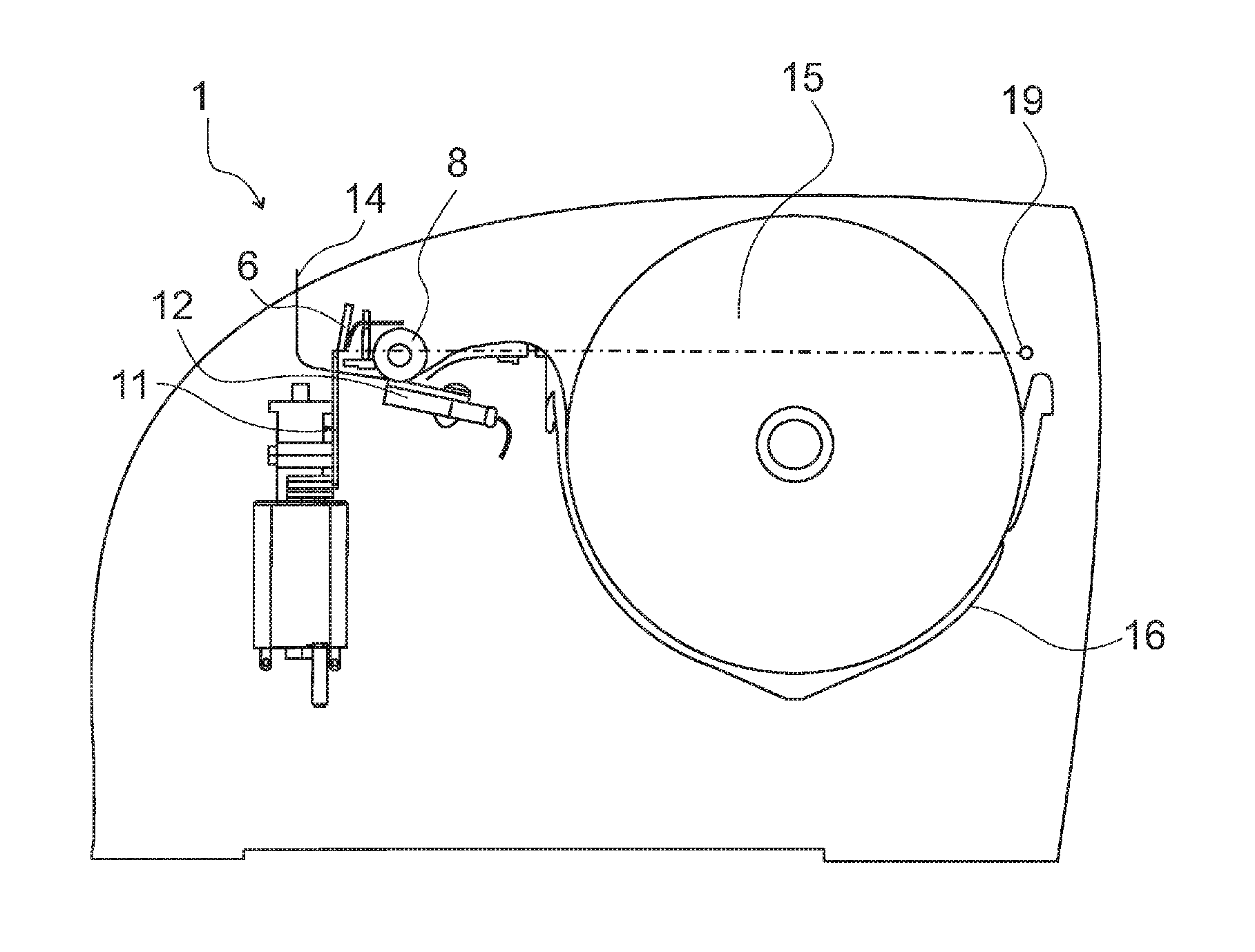
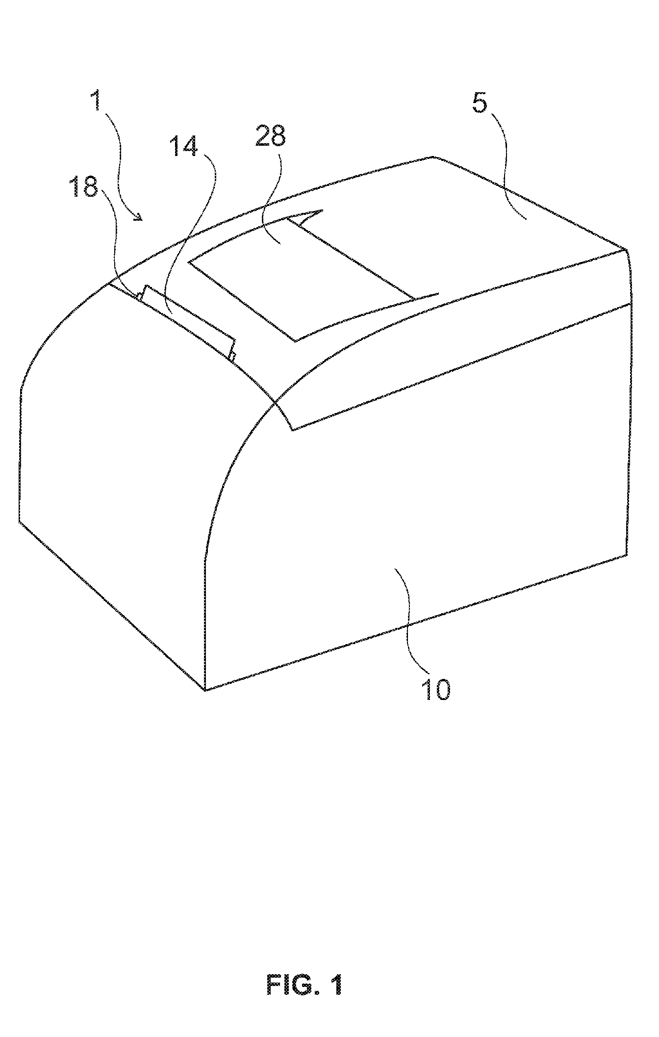
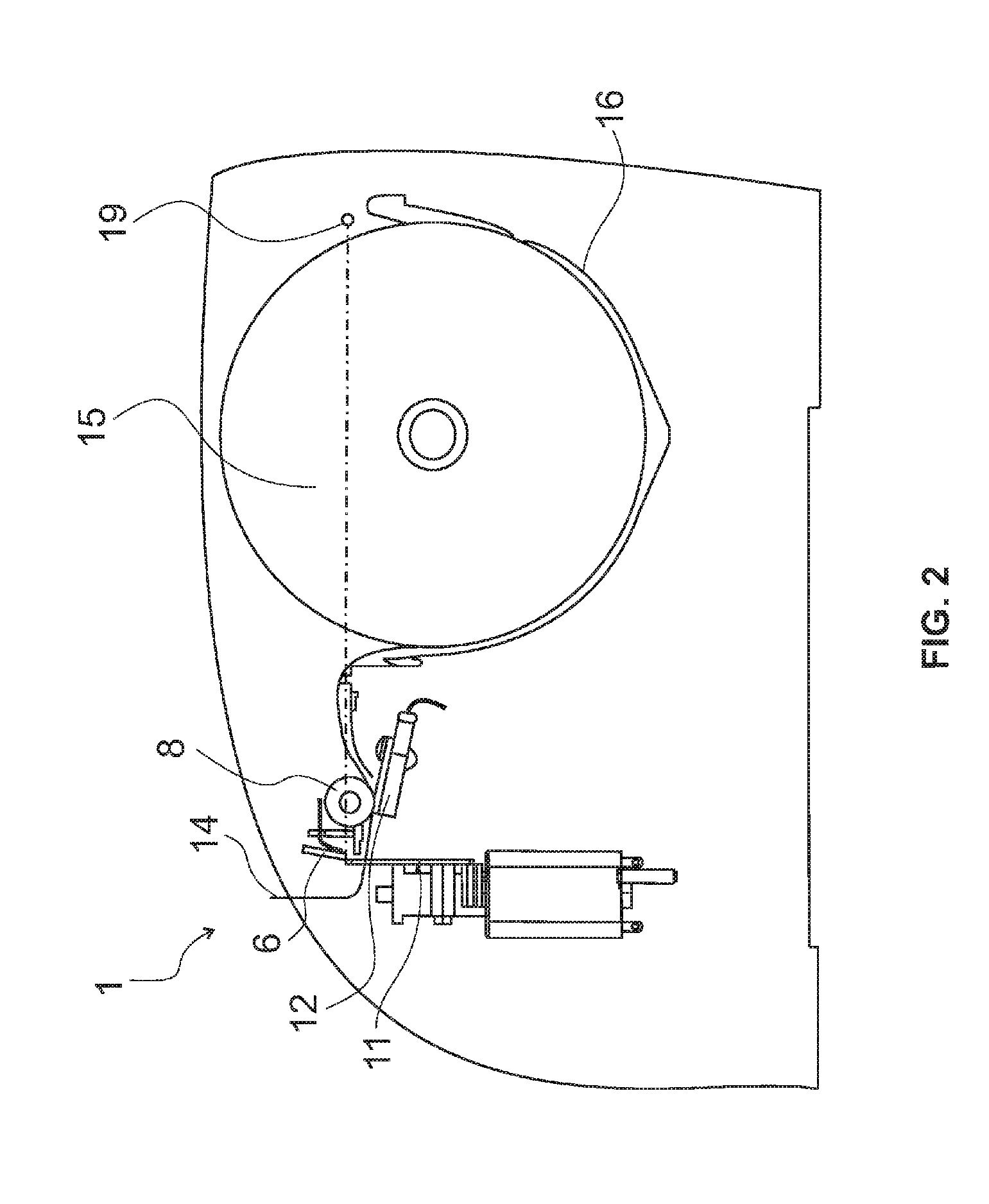
[0068]The several execution modes of the present invention are not limited to constructive details disclosed on this description and figures, as the present invention may be performed by other equivalent embodiments. According to the referred figures, the present invention refers to a thermal printer (1) with thermal printer opening mechanism (2) in two chassis, hereinafter mentioned as first chassis (3) and second chassis (4). Second chassis (4) is preferably positioned on printer cover (5), having the fixed blade (6) from cutting mechanism (7) and platen roller (8) from thermal printing mechanism (9) positioned on it, whereas first chassis (3) is preferably fixed to printer body (10) having movable blade (11) from cutting mechanism (7) and thermal head (12) from thermal printing mechanism (9) positioned on it.

[0069]In order to provide necessary locking of cover during printing and easy opening during operations such replacing paper roll, the opening mechanism (2) disclosed further...


PUM


Abstract

THERMAL PRINTER comprised by two chassis, first chassis (3) having movable blade (11) from cutting mechanism (7), thermal head (12) from thermal printing mechanism (9), automatic activation mechanism from movable blade and tracking mechanism from platen roller (8), and second chassis (4) wherein fixed blade of the cutting mechanism, and platen roller of the thermal printing mechanism are positioned. Thermal head is horizontally placed allowing paper direction to frontal part from printer, and platen roller is placed right above thermal head. On frontal part, there is a vertical cutting mechanism with slightly inclination so that mobile blade movement direction in perpendicular to line formed between cover rotation axis and the contract point between both blades.

Description

TECHNICAL FIELD[0001]The present invention refers to a technical field of selective printing mechanisms, characterized by selective application of heat to a printing material that is sensitive to heat, which uses a thermal head. More particularly, it refers to mechanisms of easy paper feed with system for automatic alignment of the platen roller, having a thermal head for printing after paper feed, additionally having a system for positioning and aligning of blades for a paper cutting device.BACKGROUND ART[0002]Printers are peripherals acting as output device widely used for data transfer such as a text or figure from digital files to a physical form like paper. The main types of printers are matrix, thermal, and inkjet, being colored or monochromatic.[0003]However, matrix printers are noisy and inkjet printers do not allow high-speed printing. Thus, the use of thermal printers increased very much over past years, particularly in points of sales, banking terminals, and label printin...

Claims


Application Information

Patent Timeline
Patent Type & Authority Applications(United States)
IPC IPC(8): B41J25/304B41J2/325
CPCB41J15/042B41J11/70
Inventor TRAUER, RICARDOCAMPOS FILHO, MARCELINO CANELADADUPUY, EDUARDO TERRABLANK, PAULO RICARDO FONSECAPEREIRA, FERNANDO AUGUSTOKIDO, LUIS EDUARDO LIMA
Owner ELGIN SA
Why Eureka
Try Eureka