
Memory heat-dissipating mechanism

a heat dissipation mechanism and memory technology, applied in the direction of cooling/ventilation/heating modification, printed circuit board receptacles, semiconductor/solid-state device details, etc., can solve the problems of shortening the life of the memory module, affecting the performance of the cpu, and increasing the generation of memory modules, etc., to facilitate the alignment with the locking holes

Inactive Publication Date: 2009-09-03
WALTON CHAINTECH CORPORATION
View PDF22 Cites 47 Cited by
  • Summary
  • Abstract
  • Description
  • Claims
  • Application Information

AI Technical Summary

Benefits of technology

[0012]The present invention has advantageous effects as follows. The heat dissipater having heat-dissipating pillars is mounted on at least two memory devices that are arranged in parallel, thereby utilizing the space above the memory device and achieving the heat dissipation of the memory module by air cooling. In comparison with the conventional art, the present invention avoids from occupying the distance between left and right sides of adjacent memory modules. In this way, the present invention can be applied to the main boards of various specifications, and thus four memory modules can be inserted thereon if desired.
[0013]Next, the heat dissipater is provided with fixing slots, so that the position of the heat dissipater can be adjusted to facilitate the alignment with the locking holes of the memory device. In this way, the present invention can be applied to the main board of various specifications.
[0014]In order to further understand the characteristics and technical contents of the present invention, the present invention will be explained with reference to the following description and accompanying drawings. However, the drawings are illustrative only and are not used to restrict the scope of the present invention.

Problems solved by technology

On the other hand, since the memory capacity of a memory module is expanding and operates at a high speed with the CPU, the heat generated by the memory module continue to increase, which may affect the CPU performance.
Furthermore, if the heat cannot be dissipated efficiently, the memory module life span would shorten and eventually fail.
Although the above-mentioned patent can dissipate the heat in practice, its volume is bulky, which occupies a lot of space within the computer and thus makes difficult the arrangement of other electronic elements within the computer.
Therefore, the heat sink disclosed in the above-mentioned patent merely allows one or two memory modules to be inserted on the main board, but it cannot allow more than three memory modules to be inserted thereon.
Thus, although the heat sink disclosed in the above-mentioned patent can dissipate the heat, it also has the drawback of occupying space.

Method used


Image

  • Memory heat-dissipating mechanism
  • Memory heat-dissipating mechanism
  • Memory heat-dissipating mechanism

Examples


Embodiment Construction

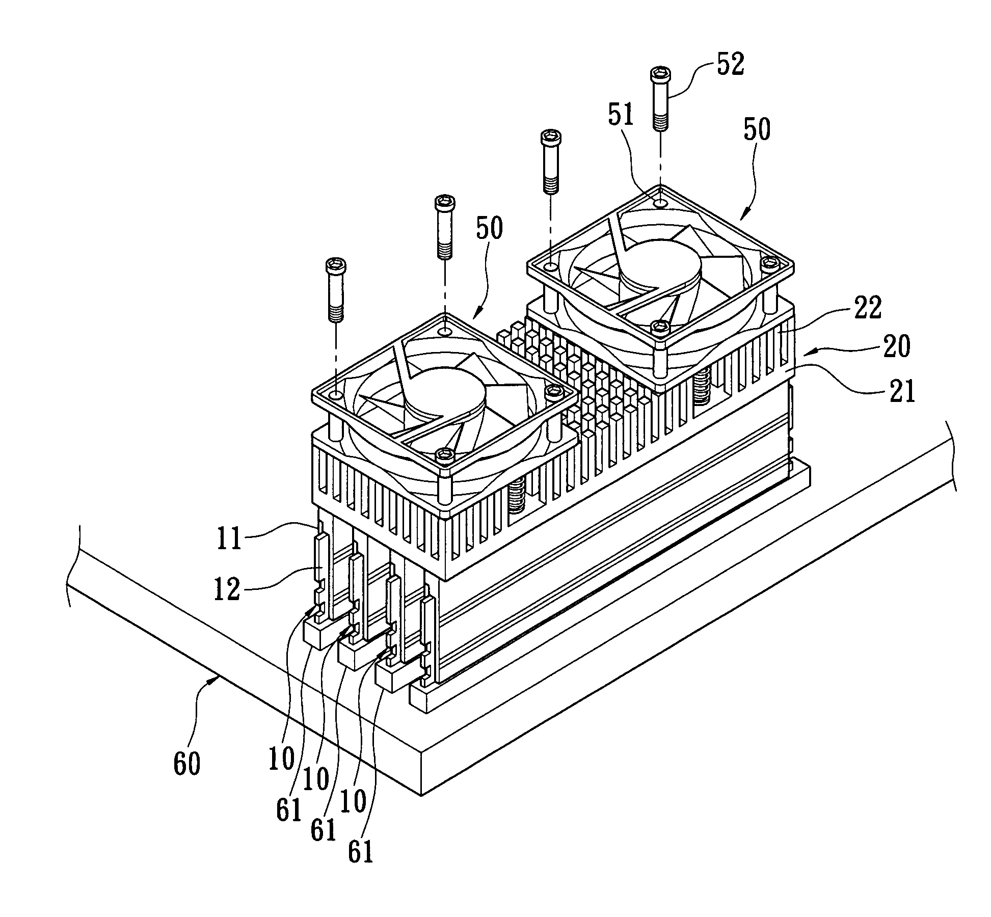
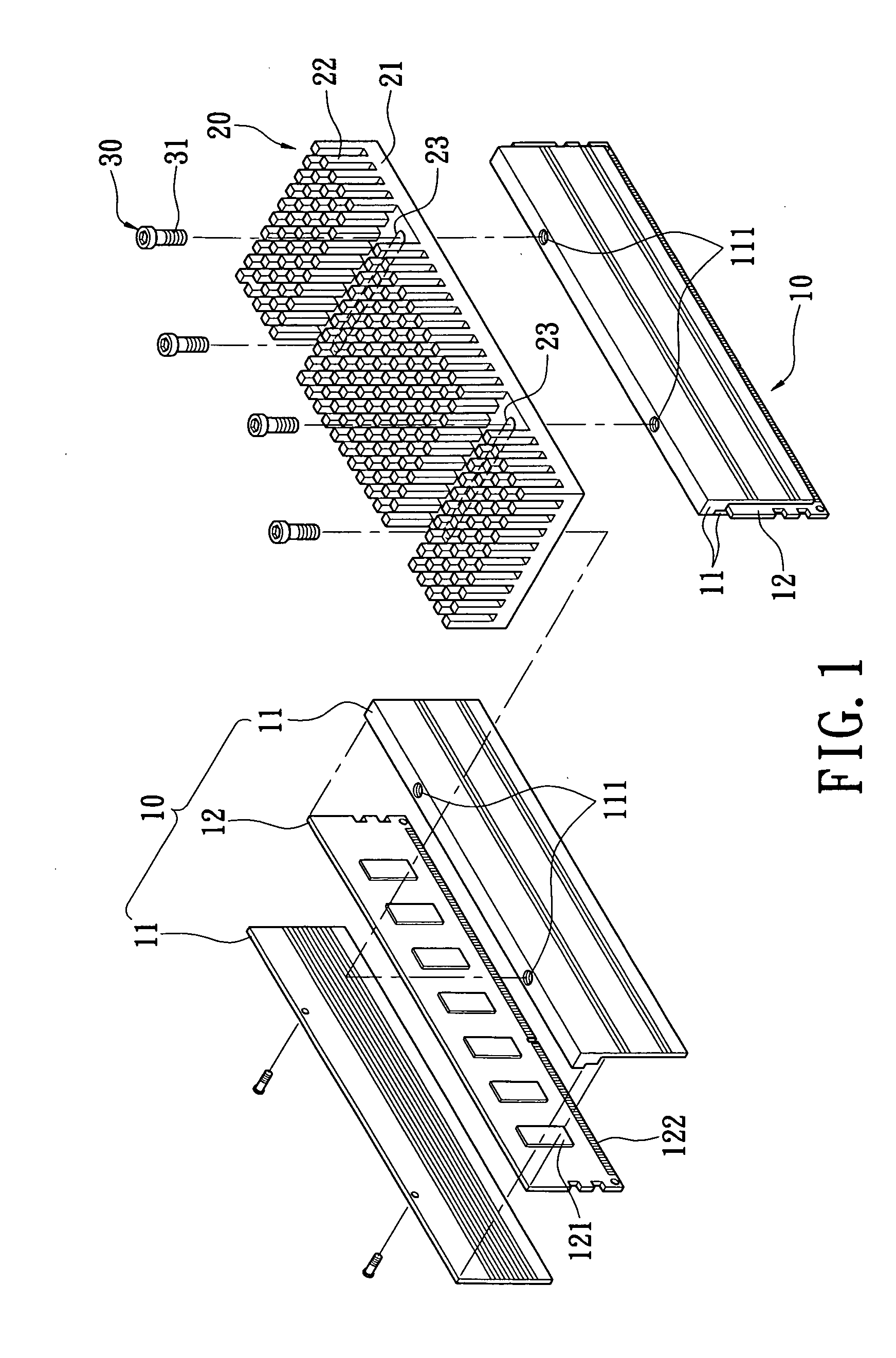
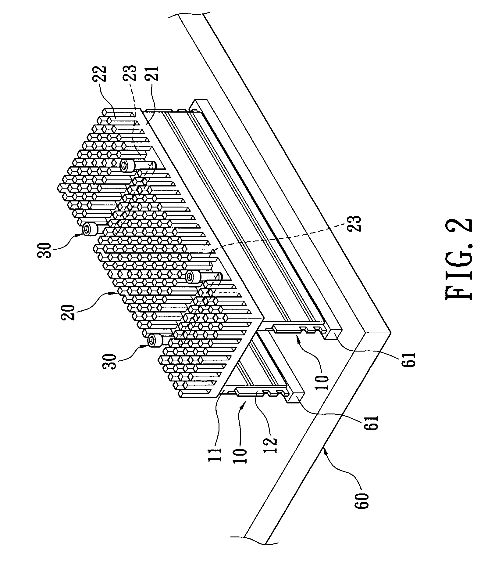
[0019]Please refer to FIG. 1. The present invention provides a memory heat-dissipating mechanism, which includes at least two memory devices 10, a heat dissipater 20, and a plurality of screw components 30.

[0020]Each memory device 10 comprises two inter-cooperating heat-dissipating pieces 11, and a memory module 12 sandwiched between two heat-dissipating pieces 11. Two heat-dissipating pieces 11 can be made by means of connecting two corresponding portions with each other. Alternatively, one heat-dissipating piece is larger than the other, and both heat-dissipating pieces are connected with each other by means of screw tightening. In the present invention, the way of connecting two heat-dissipating pieces is not limited to any specific form. Two heat-dissipating pieces 11 are used to sandwich and abut against memory chips 121 of memory module 12, so that the heat generated can be transferred to heat-dissipating pieces 11. The top surfaces of heat-dissipating pieces 11 of each memory...


PUM


Abstract

A memory heat-dissipating mechanism includes: at least two memory devices, a heat dissipater, and a plurality of screw components. Each memory device comprises two inter-cooperating heat-dissipating pieces and a memory module sandwiched between the two heat-dissipating pieces. The heat-dissipating pieces of each memory device are provided thereon with locking holes. The heat dissipater comprises a base, a plurality of heat-dissipating pillars extending from the base, and a plurality of fixing slots. Each fixing slot corresponds to the locking hole of each memory device. The top surface of the heat-dissipating piece of each memory device abuts against a bottom surface of the base of the heat dissipater. The screw components penetrate the fixing slots of the heat dissipater respectively to be screwed into the locking holes of corresponding memory device, thereby secure the heat dissipater. Via this arrangement, the present invention can dissipate the heat of the memory module.

Description

BACKGROUND OF THE INVENTION[0001]1. Field of the Invention[0002]The present invention is related to a memory heat-dissipating mechanism, and in particular to a memory heat-dissipating mechanism for dissipating the heat of a memory module and avoiding from occupying the distance between left and right sides of adjacent memory modules.[0003]2. Description of Related Art[0004]With the continuous progress of modern computer technology, the computers are gradually developed to have powerful operation function and high operation speed. Further, with computer design field gearing towards high speed and high frequency, it is necessary to dissipate the heat of CPU on a main board by means of a heat-dissipating device. On the other hand, since the memory capacity of a memory module is expanding and operates at a high speed with the CPU, the heat generated by the memory module continue to increase, which may affect the CPU performance. Furthermore, if the heat cannot be dissipated efficiently,...

Claims


Application Information

Patent Timeline
IPC IPC(8): H05K7/20
CPCH01L23/4006H01L23/467H05K7/1431H01L2924/0002H01L2924/00
Inventor LIN, JUI-NAN
Owner WALTON CHAINTECH CORPORATION
Learn More