Check patentability & draft patents in minutes with Patsnap Eureka AI!

Image decoding device and image decoding method

a decoding device and image technology, applied in the field of image decoding devices and image decoding methods, can solve the problems of decoding errors, poor quality of displayed images, and unit areas where decoding errors have occurred, and achieve the effect of suppressing deterioration of displayed image quality, effective error compensation, and effective suppression of deterioration of image quality

Inactive Publication Date: 2009-09-03
SOVEREIGN PEAK VENTURES LLC
View PDF3 Cites 9 Cited by
  • Summary
  • Abstract
  • Description
  • Claims
  • Application Information

AI Technical Summary

Benefits of technology

[0044]According to the present invention, error compensation is performed not only for the unit area (the unit in decoding) where the decoding error occurs within the frame of the image, but also for a pixel included in another unit area than the unit area, which may be influenced by this decoding error. As a result, even when the decoding error occurs in image decoding while filtering at a boundary of the unit area, it is possible to suppress deterioration of the quality of a displayed image.
[0045]Moreover, determining the error compensating area for which the error compensation should be performed based on the judgment of filtering execution enables to perform effective error compensation. Furthermore, not performing the error compensation for pixels that do not need the error compensation enables to effectively suppress deterioration of the quality of the displayed image.
[0046]In addition, the error compensation is performed by replacing the value of the pixel included in the error compensating area with the value of the prior frame, the value of the other pixel in the same frame, or the fixed value, thereby suppressing deterioration of the quality of image with ease and effectively.

Problems solved by technology

In this case, it is judged that a decoding error occurs.
Here, since the pixel value of the unit area, where the decoding error has occurred, is not used, if the unused unit area is left as it is, the quality of a displayed image becomes poor.
For this reason, not only the unit area where the decoding error has occurred, but also the pixel of neighboring unit area, in which the de-block filtering is performed by using the pixel included in the unit area where the decoding error has occurred, becomes unstable.
For this reason, in the conventional technology, the bad influence remains in the image quality of this neighboring pixel, and there is a problem that causes deterioration in the displayed image.
Thus, the quality of the displayed image becomes poor.

Method used


Image

  • Image decoding device and image decoding method
  • Image decoding device and image decoding method
  • Image decoding device and image decoding method

Examples


embodiment 1

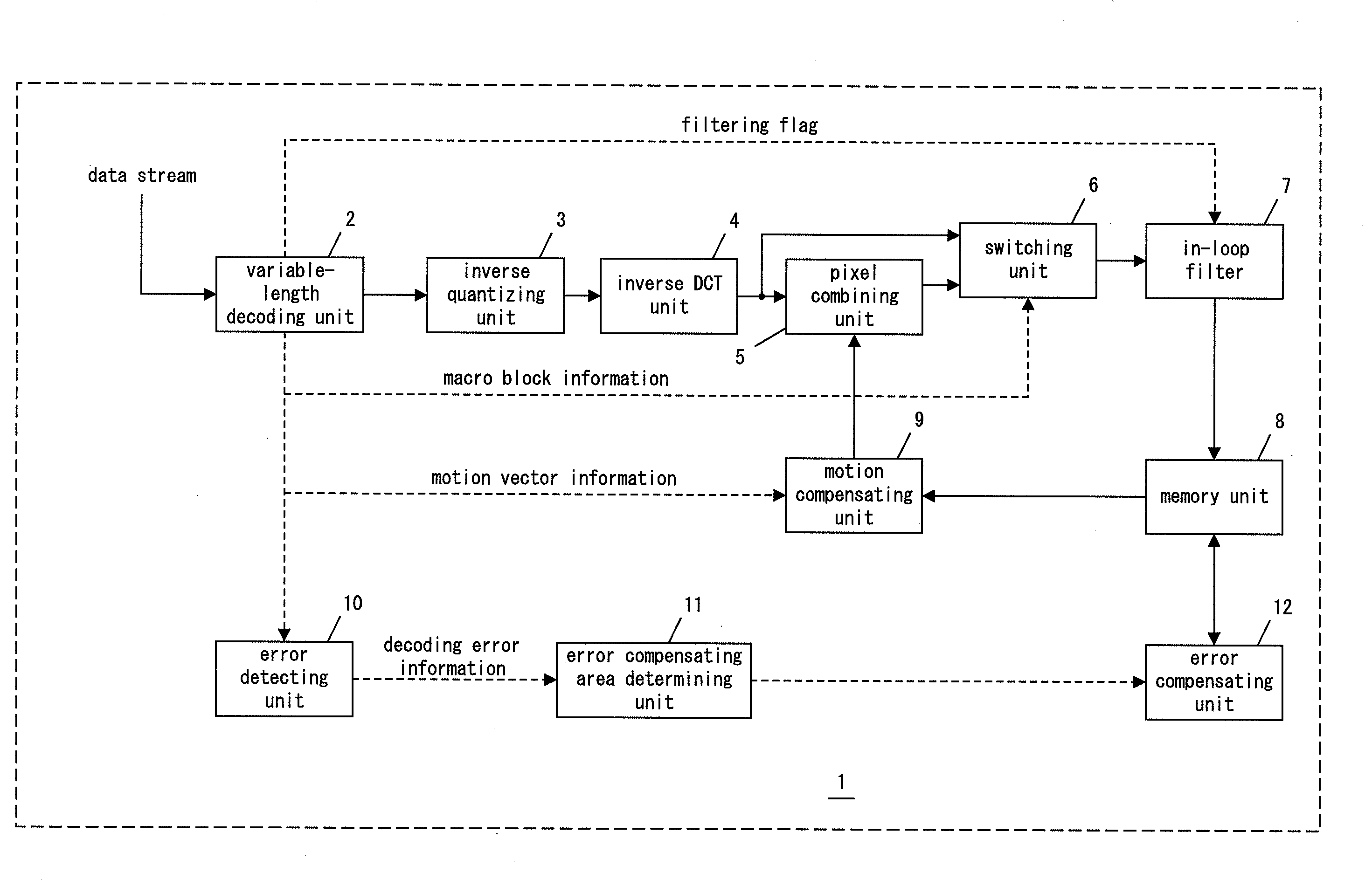
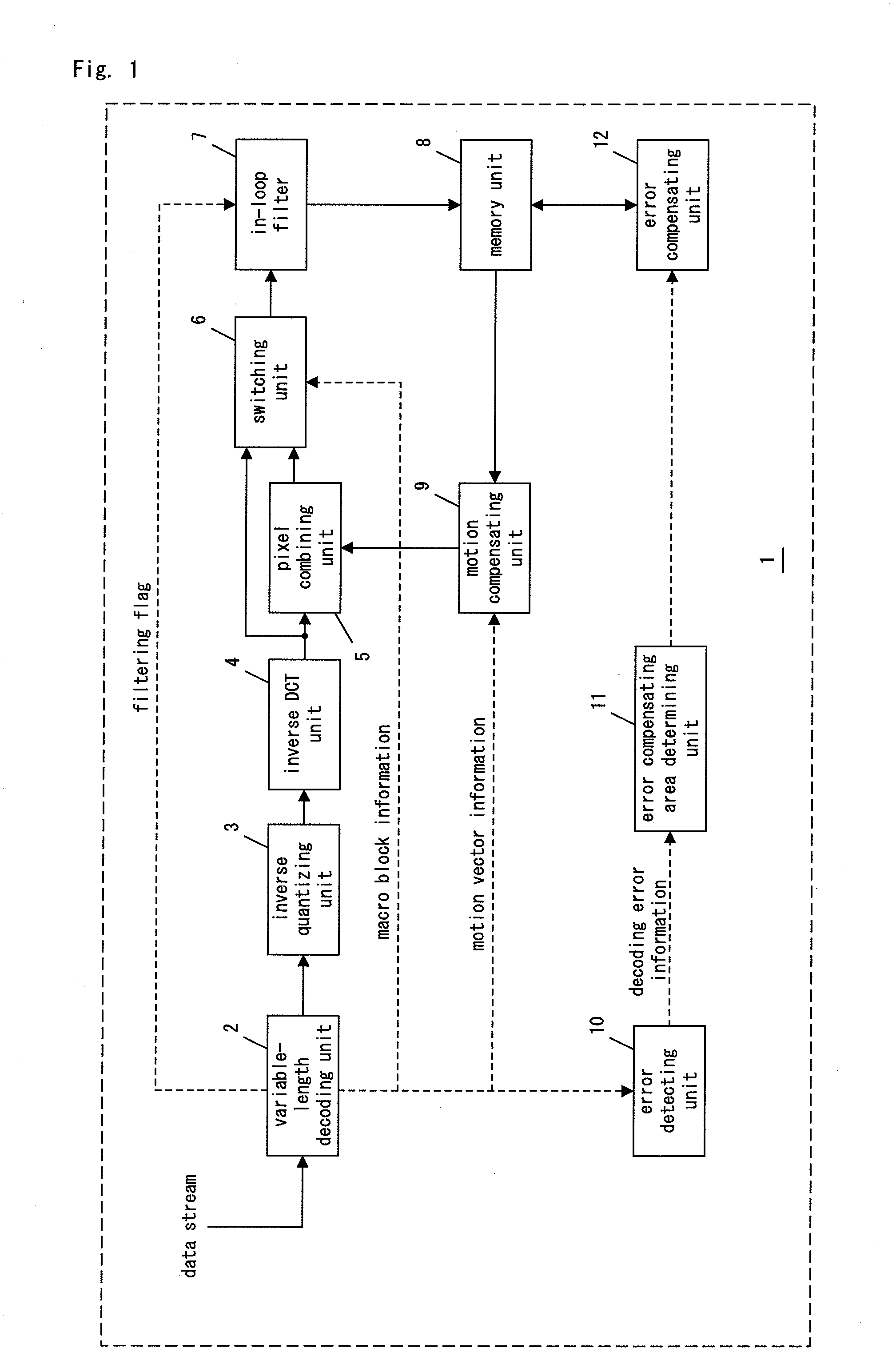
[0077]FIG. 1 and FIG. 2 are block diagrams of an image decoding device in Embodiment 1 of the present invention.

[0078]First, construction of the image decoding device 1 will now be explained.

[0079]The image decoding device I decodes an encoded data stream.

[0080]The data stream is inputted into a variable-length decoding unit 2. The variable-length decoding unit 2 performs variable-length decoding on the inputted data stream. In particular, the variable-length decoding unit 2 analyzes a header included in the inputted data stream, and further decodes the variable-length encoded data stream, referring to a variable-length encoding table.

[0081]First, the variable-length decoding unit 2 detects a start code included in a data stream, and then decodes various parameters from header information included in the following start code. At this time, the variable-length decoding unit 2 also detects a filtering flag included in a slice defined in standards, such as H.264 and H.263. The variable...

embodiment 2

[0142]Embodiment 2 will now be explained in the following.

[0143]The image decoding device 1 of Embodiment 2 switches the error compensating areas based on whether the filtering in the in-loop filter 7 will be executed or not.

[0144]FIG. 7 is a block diagram of an image decoding device in Embodiment 2 of the present invention.

[0145]The image decoding device 1 shown in FIG. 7 newly comprises a judging unit 30.

[0146]The judging unit 30 judges whether the filtering using the pixel included in the different unit area in the in-loop filter 7 will be executed or not. The judging unit 30 judges whether or not the filtering will be executed by using a filtering flag included in a header that is analyzed by the variable-length decoding unit 2 (or the arithmetic decoding unit 13). The filtering flag includes information which the filtering will be executed or not. The judging unit 30 outputs the judgment result to the error compensating area determining unit 11.

[0147]When the judging unit 30 ju...

embodiment 3

[0174]FIG. 11 is a block diagram of a semiconductor integrated circuit in Embodiment 3 of the present invention.

[0175]A semiconductor integrated circuit 40, in general, is composed of an MOS transistor. A specific logic circuit is realized by the connection construction of the MOS transistor. In recent years, the level of integration of the semiconductor integrated circuit has been improved; thus, it is possible to realize a very complicated logic circuit (for example, the image decoding device of the present invention) can be realized by one semiconductor integrated circuit or a couple of semiconductor integrated circuits.

[0176]The semiconductor integrated circuit 40 comprises the image decoding device 1 explained in Embodiments 1 and 2.

[0177]Depending on the necessity, the semiconductor integrated circuit 40 may comprise an image encoding device 41, a sound processing unit 42, a display controlling unit 43, and an ROM 44.

[0178]Furthermore, the semiconductor integrated circuit 40 m...


PUM


Abstract

An image decoding device (1) comprises: an error detecting unit (10) operable to detect a decoding error in each unit area in one frame of an image; an error compensating area determining unit (11) operable to determine an error compensating area for which error compensation should be performed for the decoding error; and an error compensating unit (12) operable to perform error compensation to the error compensating area. The error compensating area determining unit (11) determines a unit area where the decoding error occurs, and a predetermined area adjacent to the unit area, as the error compensating area. The image decoding device (1) provides suppression of the quality of an image displayed after decoding.

Description

TECHNICAL FIELD[0001]The present invention relates to an image decoding device operable to effectively perform error compensation when a decoding error occurs in decoding of compressed image data, and an image decoding method related thereto.BACKGROUND ART[0002]MPEG 2 and MPEG 4 are used as encoding systems of moving pictures. In these days, “H.264 / MPEG 4 AVC” (it's called as “H.264” hereinafter), whose compression efficiency is further improved comparing to MPEG 4, is standardized by the Joint Video Team (it's called as “JVT” hereinafter).[0003]FIG. 13 is a block diagram of an image decoding device standardized by MPEG 4.[0004]A variable-length decoding unit 100 decodes a variable-length encoded data stream according to a variable-length encoding table. An inverse AC / DC predicting unit 101 performs AC / DC prediction, and outputs quantized coefficients QF [x][y]. An inverse quantizing unit 102 outputs DCT coefficients F [x][y] by performing inverse quantization on the quantized coeff...

Claims


Application Information

Patent Timeline
Patent Type & Authority Applications(United States)
IPC IPC(8): H04B1/66H04N19/102H04N19/117H04N19/895H04N19/134H04N19/166H04N19/174H04N19/176H04N19/186H04N19/42H04N19/44H04N19/50H04N19/503H04N19/523H04N19/61H04N19/625H04N19/65H04N19/67H04N19/82H04N19/89H04N19/91
CPCH04N19/61H04N19/174H04N19/895H04N19/527H04N19/82
Inventor TOMITA, HIROTOHASHIMOTO, TAKASHI
Owner SOVEREIGN PEAK VENTURES LLC
Features
  • R&D
  • Intellectual Property
  • Life Sciences
  • Materials
  • Tech Scout
  • Unparalleled Data Quality
  • Higher Quality Content
  • 60% Fewer Hallucinations
Learn More