Method for producing retardation film

Inactive Publication Date: 2009-09-03
ZEON CORP
View PDF4 Cites 13 Cited by
  • Summary
  • Abstract
  • Description
  • Claims
  • Application Information

AI Technical Summary

Benefits of technology

[0024]In a method for producing a retardation film according to the present invention, a retardation film with a large are

Problems solved by technology

However, it is difficult to produce the retardation film having a la

Method used


Image

  • Method for producing retardation film
  • Method for producing retardation film

Examples


example 3

Producing Example 3

[0107]A laminated film 3 being 1350 mm in width and 180 μm in thickness composed of the polycarbonate resin layer (layer A: 10 μm) and the styrene maleic anhydride copolymer resin layer (layer B: 170 μm) was obtained in the same manner as in PRODUCING E EXAMPLE 1, except that the thickness of layer A Was adjusted to 10 μm and the thickness of layer B was adjusted to 170 μm.

example 4

Producing Example 4

[0108]A laminated film 4 being 1350 nom in width and 180 μm in thickness composed of the polycarbonate resin layer (layer A: 80 μm) and a polystyrene resin layer (layer B: 90 μm) was obtained in the same manner as in PRODUCING EXAMPLE 1, except that the polystyrene resin (made by Japan Polystyrene Inc., HF44, a deflection temperature under load is 73° C.) was used in place of Dylark D332, the thickness of layer A was adjusted to 80 μm and the thickness or layer B was adjusted to 90 μm.

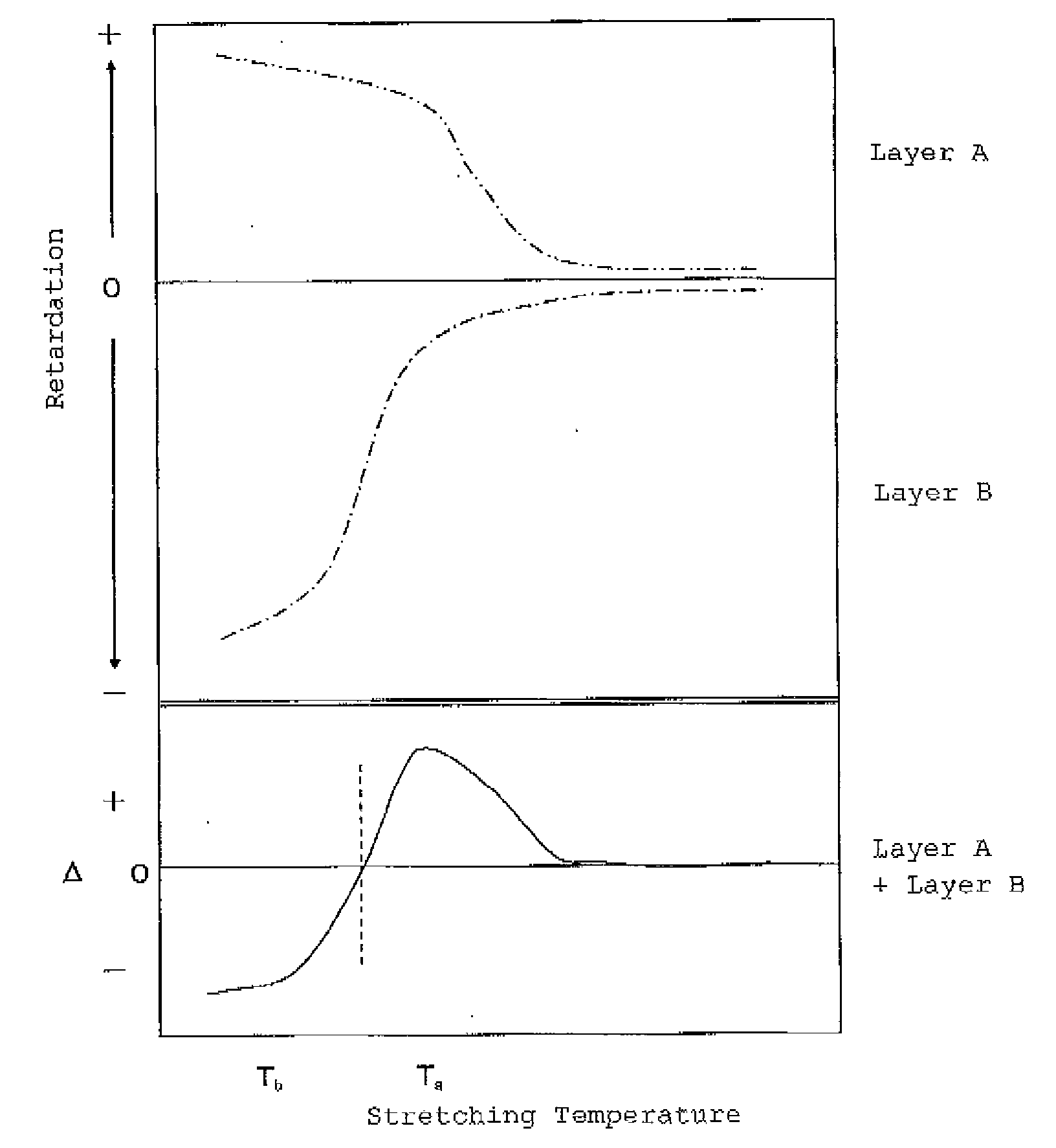
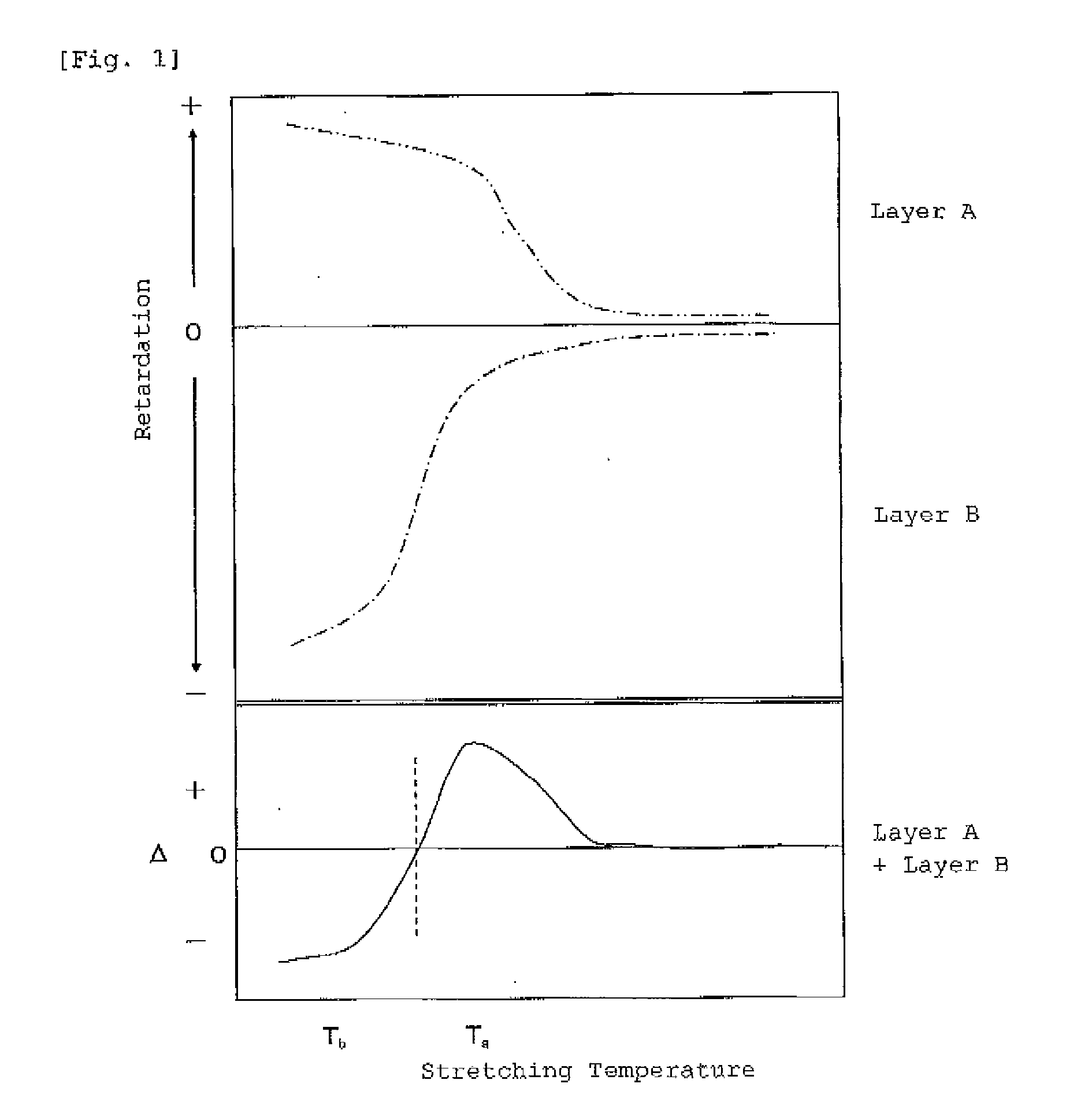
[0109]The laminated films 1 to 4 were uniaxially stretched by 1.25 times of stretching ratio in various temperatures in a longitudinal direction of the film, Table 1 shows the lag in a phase of which linearly polarized light entering vertically into the film plane and having an oscillating surface of an electric vector in an X-Z plane against linearly polarized light entering vertically into the film plane and having a oscillating surface of an electric vector in a Y-Z plane, in whic...

example 1

[0111]The laminated film 1 obtained in PRODUCING EXAMPLE 1 was supplied to a longitudinal uniaxially stretching machine, and the film was stretched in a longitudinal direction at a stretching temperature of 145° C. by a stretching magnification of 1.5 times.

[0112]Then, the stretched film was supplied to the tenter stretching machine, the film was stretched in a transverse direction at a stretching temperature of 130° C. by a stretching magnification of 1.25 times, and a retardation film 1 was obtained. The evaluation results are Shown in Table 2.


PUM

PropertyMeasurementUnit
Angleaaaaaaaaaa
Angleaaaaaaaaaa
Elongationaaaaaaaaaa

Abstract

A method for producing a retardation film comprising the steps of: (a) uniaxially stretching an original film for producing retardation film in one direction at either a temperature T1 or T2; and then (b) uniaxially stretching the film stretched in the step (a) in a direction perpendicular to the above-mentioned direction of stretching at a temperature T2 or T1 different from the above-mentioned temperature, in which the original film for producing retardation film has a characteristic that a phase of linearly polarized light entering vertically into the film plane and having an oscillating surface of an electric vector in an X-Z plane against linearly polarized light entering vertically into the film plane and having an oscillating surface of an electric vector in a Y-Z plane lags by uniaxially stretching in the direction of the X axis at a temperature T1, and leads by uniaxially stretching in the direction of the X axis at a temperature T2 different from the above-mentioned temperature T1, in which the X axis is an uniaxially stretching direction, the Y axis is a direction perpendicular to the uniaxially stretching direction in the film plane, and the z axis is a direction of a thickness of the film.

Description

TECHNICAL FIELD[0001]The present invention relates to a method for producing a retardation film. More particularly, the present invention relates to a method for producing a retardation film suitable for birefringence compensation of a liquid crystal display device.BACKGROUND OF THE ART[0002]To decrease dependence of a color tone in a liquid crystal display device on an angle, a retardation film which satisfies a relation of 0.92≦R40 / Re≦1.08, in which Re is a retardation value at an incident angle of 0 degrees, and R40 is a retardation value at an incident angle of 40 degrees, or a retardation film which satisfies a relation of nx>nz>ny, in which nx is a refractive index in a slow axis direction in a plane, ny is a refractive index in a direction at a right angle to the slow axis direction in the plane, and nx is a refractive index in a thickness direction, have been proposed.[0003]For example, Patent Document 1 discloses that a first anisotropic film is obtained by uniaxially...

Claims


Application Information

Patent Timeline
IPC IPC(8): B32B27/36B29C55/04B32B7/00B32B7/023
CPCB29C55/023B29C55/14B29K2995/0034Y10T428/2495B32B27/08G02B5/3083G02F1/133634B32B7/02B32B23/08B32B23/20B32B27/18B32B27/20B32B27/22B32B27/286B32B27/302B32B27/304B32B27/306B32B27/308B32B27/32B32B27/36B32B27/365B32B2264/0235B32B2264/025B32B2264/102B32B2264/104B32B2270/00B32B2307/306B32B2307/40B32B2307/42B32B2307/516B32B2307/558B32B2307/71B32B2307/744B32B2457/202B32B2264/04Y10T428/31507B29K2025/06B29K2069/00C08J2325/06C08J2369/00B32B7/023G02F1/13363G02B5/30B29D11/00644B29D11/00788C08J5/18
Inventor HATANO, TAKU
Owner ZEON CORP
Why Eureka
Try Eureka