Support Arm for a Work Machine

a technology for supporting arms and work machines, which is applied in mechanical machines/dredgers, soil shifting machines/dredgers, constructions, etc., can solve the problems of high cost, complex production and inspection of such welding seams, and relatively complicated cross-sections to manufacture, so as to achieve the lowest intrinsic mass and manufacturing with a minimum of effort.

Inactive Publication Date: 2009-09-10
CNH IND AMERICA LLC
View PDF24 Cites 14 Cited by
  • Summary
  • Abstract
  • Description
  • Claims
  • Application Information

AI Technical Summary

Benefits of technology

[0005]The task of the invention is to produce a support arm of the type described that follows the component stresses to be expected to a high degree, has the lowest possible intrinsic mass, and can be manufactured with a minimum of effort.
[0007]Advantageously, the at least one wall is made of a single-piece plate-shaped element, but in an additional design it is possible for the at least one wall to be comprised of several plate-shaped elements that are welded together. It is preferable for the at least one plate-shaped element to have a uniform wall thickness. To enable ideal adaptation to the component stresses to be expected, it is advantageous to design the corresponding plate-shaped element with several cut-outs. The cut-outs can be designed according to the load curve to be expected.
[0008]Therefore a support arm with walls of the type described is suggested that is adapted to a high degree to the load curve expected for the component due to the cut-out(s) that can be designed accordingly. The cut-outs are correspondingly intended for those areas of the component where low stresses are expected. They can be manufactured without any problem and in any shape desired in the plate-shaped element. Due to the planar cut-outs, the intrinsic mass of the support arm is relatively low.

Problems solved by technology

With this well-known welded support arm construction, it is possible to realize a support arm with the lowest possible intrinsic mass while still accounting for the load curve of the particular support arm, but manufacturing such a support arm is cost-intensive due to the high number of welding seams required for the connection of plates of different thicknesses.
In addition, the production as well as the inspection of such welding seams is complex due to the high dynamic load placed on a work machine.
Such a cross-section is relatively complicated to manufacture due to the necessity of producing the additional profile-reinforced end sections.

Method used


Image

  • Support Arm for a Work Machine
  • Support Arm for a Work Machine
  • Support Arm for a Work Machine

Examples


Embodiment Construction

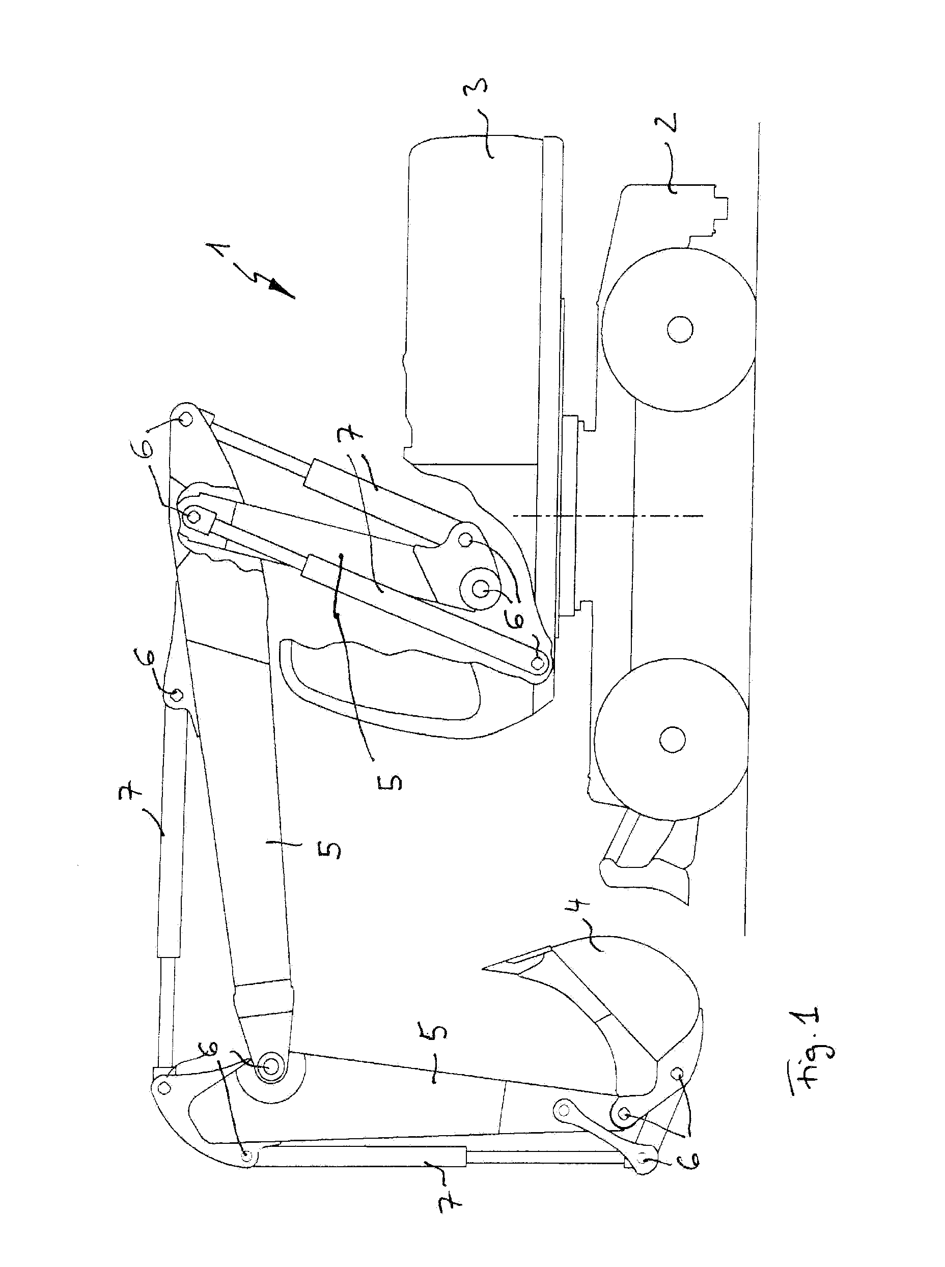
[0021]FIG. 1 shows an example of a work machine in the form of a machine generally referred to as an excavator and labeled here with 1. The following description of the design of a support arm according to the invention can be realized in general for any type of mobile or stationary work machine; excavator 1 shown in FIG. 1 is only an example of such a machine.

[0022]Excavator 1 has one lower carriage 2 and one upper carriage 3, and is equipped with a work tool in the form of a shovel 4. This shovel 4 is connected by work equipment consisting of several support arms 5 to excavator 1, and in particular to the upper carriage 3 of the same excavator. Other support arms, either individually or in combination, can also be connected to the lower carriage 2, of course, but this is not shown in detail in the drawing.

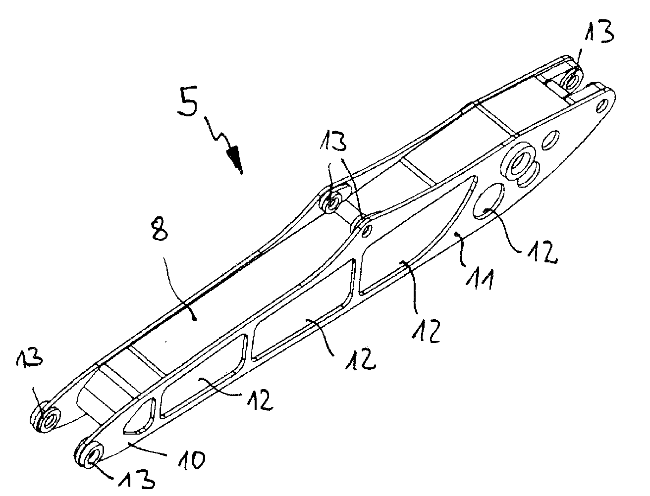
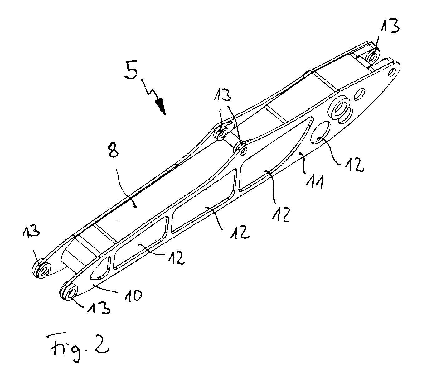
[0023]The individual support arms 5 of the work equipment of the excavator are connected by pin supports 6 to each other and to the hydraulic cylinders 7 moving the arms as well ...


PUM


Abstract

A support arm for a work machine is to be created whose design follows the component stresses to be expected to a high degree, which has the lowest possible intrinsic mass, and which can be manufactured with a minimum of effort.This is accomplished in that the support arm consists of at least one wall that has at least one plate-shaped element, which has at least one planar cut-out adapted to the component stresses expected, whereby at least one cut-out is closed off by a thin-walled cover element opposite the plate-shaped element.

Description

[0001]The invention pertains to a support arm for a work machine, for example a jib or boom on the work equipment of a excavator, with at least one wall having at least one plate-shaped element.BACKGROUND[0002]Work machines, both movable machines such as excavators, wheel loaders, tractors, telescopic handlers, or other such machines as well as stationary machines such as cranes have support arms of different types that, individually or in combination, bear or move a work tool, a support, or other components and that connect these components to the work machine. These support arms of varying length and design are often connected via a hinge to the drives moving the arm and to the machine, the work tool, the support, or other components. The support arms generally consist of a box-shaped cross-section that is formed by walls, for example upper and lower flanges, as well as by side walls. There are location points for pin supports welded onto or in the walls which connect the support ...

Claims


Application Information

Patent Timeline
Patent Type & Authority Applications(United States)
IPC IPC(8): E02F9/14E02F3/38
CPCE02F3/38E02F3/301
Inventor WILLAREDT, BERNHARDLECHLER, GERALDSCHMELING, RALFOERTEL, HOLGERDITZ, BIRGIT
Owner CNH IND AMERICA LLC
Why Eureka
Try Eureka