Method for Placing Inert Gas in Gas-Filling Packaging Machine

a gas-filling packaging machine and inert gas technology, which is applied in the direction of liquid handling, applications, caps, etc., can solve the problems of increasing the filling time, clogging the filling funnel, and the distance between the nozzle and the article, so as to improve the gas replacement rate and facilitate the operation of gas filling work smoothly and stably. , the structure of the nozzle attitude control can be simplified

Active Publication Date: 2009-09-10
GENERAL PACKER
View PDF3 Cites 11 Cited by
  • Summary
  • Abstract
  • Description
  • Claims
  • Application Information

AI Technical Summary

Benefits of technology

[0010]According to the invention described in claim 1, the distal end of the gas-filling nozzle is inserted into the packaging bag while being close near to the center of the drop mouth of the filling funnel by the nozzle attitude control unit. Accordingly, an erroneous insertion and defect of the nozzle can be resolved. More specifically, the nozzle can be prevented from disengaging from the open top of the bag when inserted into the bag. Furthermore, the nozzle can be prevented from sticking into the folds of the packaging bag of the gusset type. Additionally, since the final gas replacement is carried out while the bag top is closed by the shutter unit, the gas replacement rate is improved.
[0011]According to the invention described in claim 2, the structure of the nozzle attitude control can be simplified and a gas filling work can carried out smoothly and stably.
[0012]According to the invention described in claim 3, the method can be applied to various types of packaging bags such as a flat bag, a packaging bag having folds on both sides respectively except for the top thereof (side gusset chuck bag) or a gusset bag, whereupon a gas filling work can carried out smoothly and stably.

Problems solved by technology

There is a rare defect that the distal end of the nozzle n sticks into inwardly extending parts of the folds c.
In the latter nozzle fixing structure, the nozzle fixed to the central inside of the filling funnel constitutes a barrier to the article passing, resulting in an increase in the filling time.
As a result, the filling funnel is clogged by the article in some cases.
Furthermore, in the inert gas filling method described in the above gazette, gas replacement is not carried out while the top of the bag is closed.
Accordingly, gas replacement is sometimes unfavorable depending upon a type or size of a packaging bag or a type of the article.

Method used


Image

  • Method for Placing Inert Gas in Gas-Filling Packaging Machine
  • Method for Placing Inert Gas in Gas-Filling Packaging Machine
  • Method for Placing Inert Gas in Gas-Filling Packaging Machine

Examples


Embodiment Construction

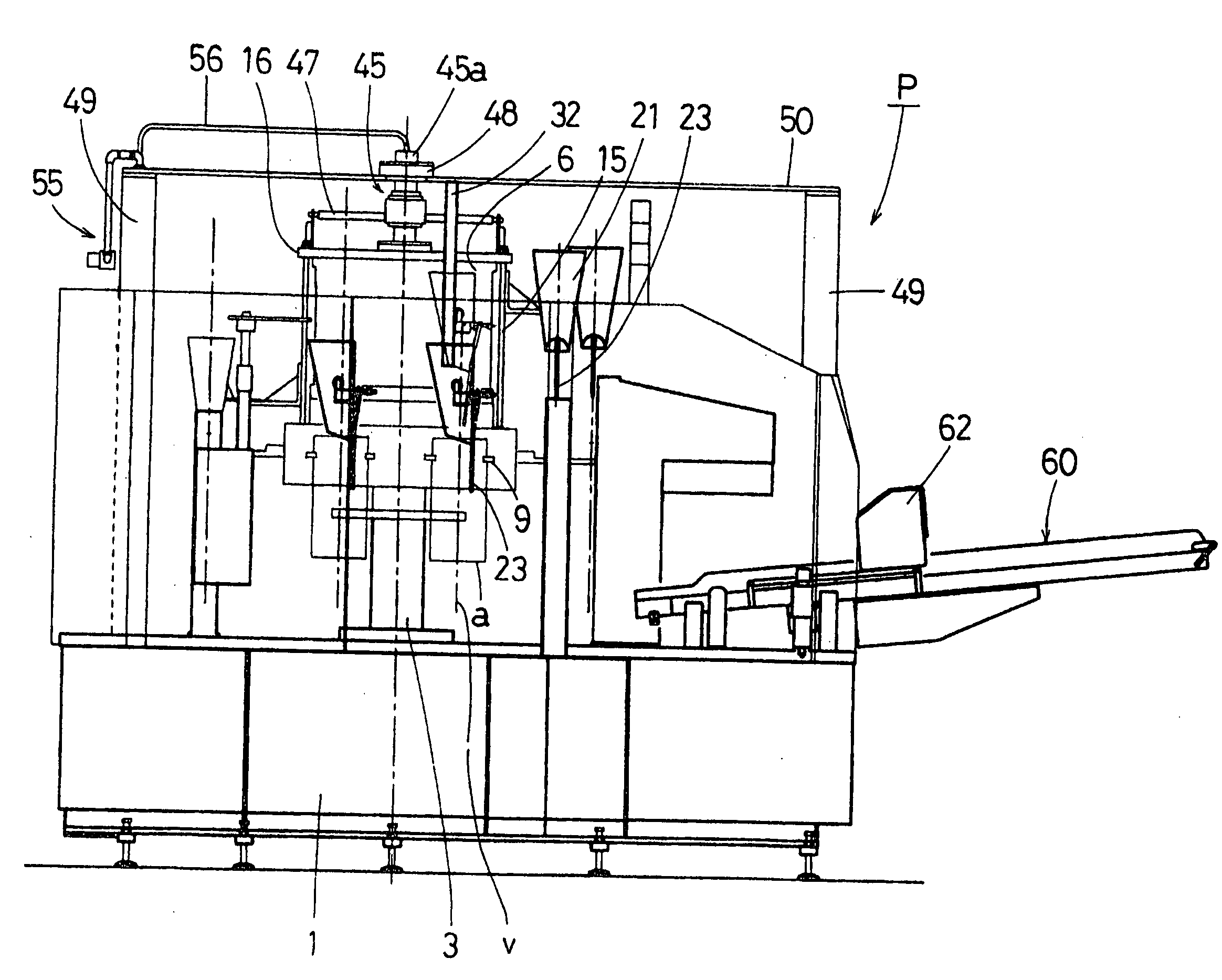
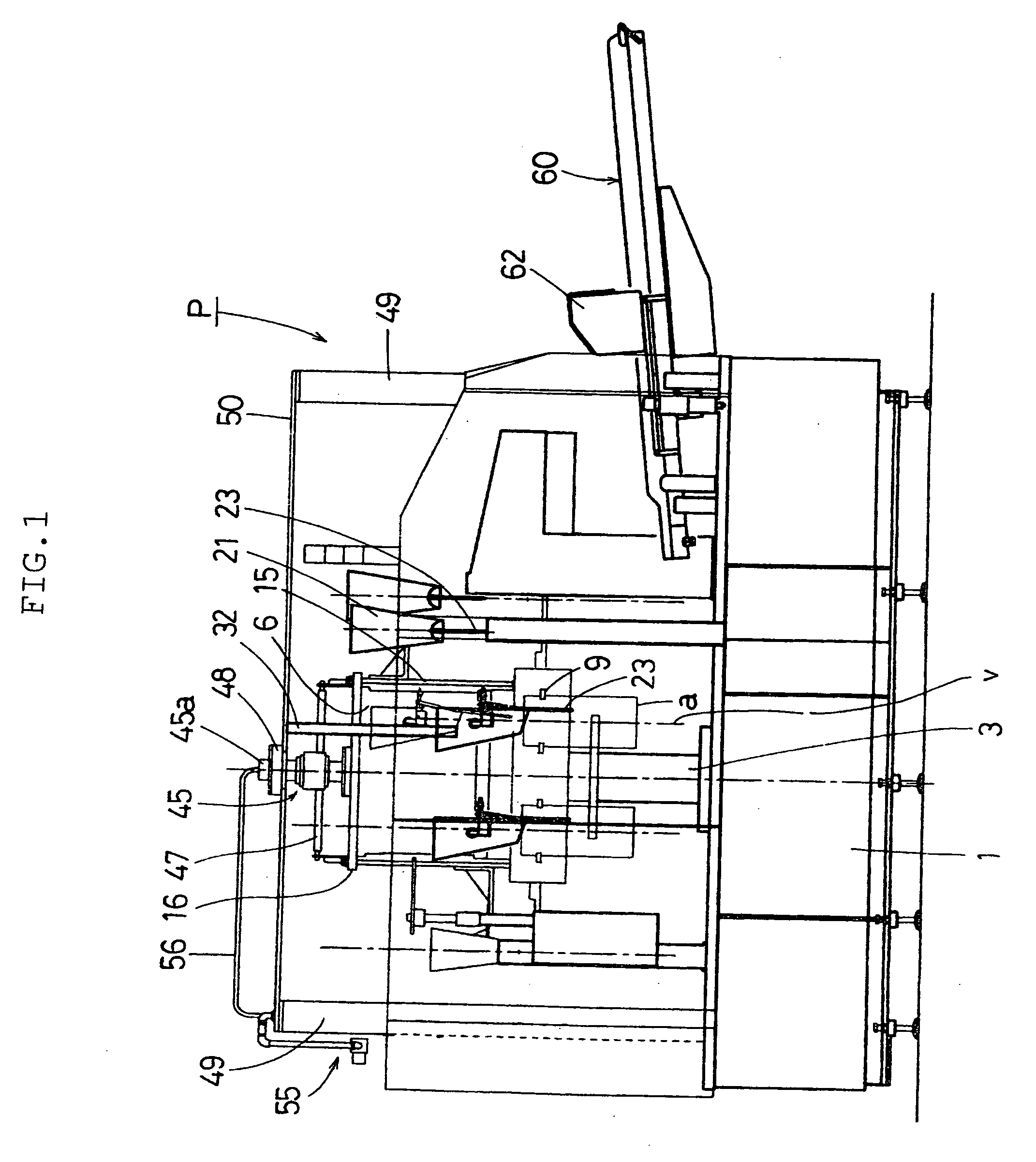
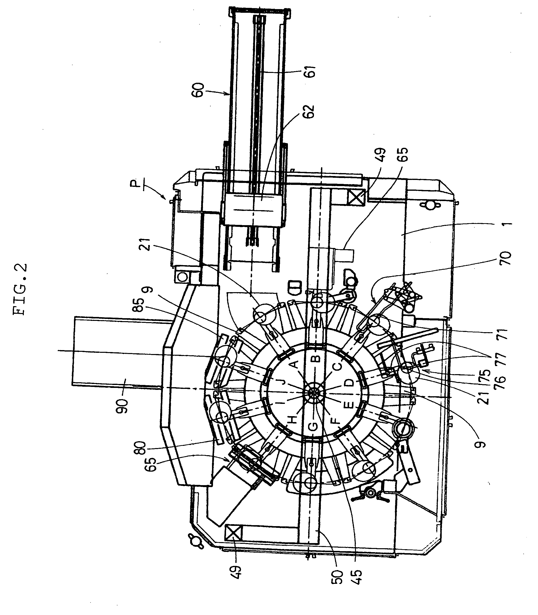
[0013]A best mode of the present invention will be described with reference to the accompanying drawings. FIG. 1 is a side view of the gas-filling packaging machine to which the method for filling a gas-filling packaging machine with an inert gas is applied. FIG. 2 is a plan view of the machine. FIG. 3 is a side view of a rotating body, a filling funnel and peripheral structure. FIG. 4 is a view explaining a nozzle attitude control unit. FIG. 5 is a development of cam rail showing the relative positional relationship among a filling funnel, gas-filling nozzle and packaging bag over a whole process. FIG. 6 is a side view of a shutter unit showing execution of gas replacement with the bag top being closed. FIG. 7 is a plan view of the shutter unit shown in FIG. 6.

[0014]FIGS. 1 and 2 show a gas-filling packaging machine P to which the method of the invention for filling a gas-filling packaging machine with an inert gas is applied. The rotary gas-filling packaging machine P comprises a ...


PUM


Abstract

[PROBLEMS] To provide an inert gas placing method for a gas-filling and packaging machine, in which troubles occurring when a gas-filling nozzle is inserted into a packaging bag are eliminated and in which a gas replacement rate is increased.[MEANS FOR OVERCOMING PROBLEMS] A gas-filling nozzle (23) is provided at a filling funnel (21) in correspondence with each grip (9) of a rotating body, and the gas-filling nozzle (23) has a forward end (23b) controlled by a nozzle attitude control unit (25) so as to approach or recede from an imaginary normal line v passing through the center of the drop opening of the filling funnel. In the process preceding a filling process, the drop opening of the filling funnel and the forward end of the gas-filling nozzle brought close to the normal line v are inserted from the opened bag opening b into a package bag a, and at the same time, the forward end is separated from the normal line v and moved toward a corner of the package bag. In the process following the filling process, inert gas jetted from the gas filling nozzle and air in the package bag are replaced with each other, and in a postprocess on the downstream side, the replacement action between the inert gas and the air is promoted with the bag opening b substantially closed by a shutter unit (65).

Description

TECHNICAL FIELD[0001]The present invention relates to a method for filling a gas-filling packaging machine with an inert gas, in which machine gas replacement is carried out by supplying the inert gas from a nozzle into a packaging bag previously filled with articles so that air in the bag is expelled out and a top of a packaging bag is subsequently sealed.BACKGROUND ART[0002]A method for filling a conventional gas-filling packaging machine with an inert gas is disclosed in JP-A-2004-67224 by the present applicant. The gas-filling packaging machine is constructed so that a single intermittently rotating table is used for filling a packaging bag with articles, filling an inert gas such as nitrogen gas and heat-sealing a top of the bag after the bag has been filled with the articles and inert gas. A nozzle for filling with the inert gas is constructed so as to be fixed to an outer surface of a filling funnel provided on a packaging bag the top of which is open. The filling funnel has ...

Claims


Application Information

Patent Timeline
Patent Type & Authority Applications(United States)
IPC IPC(8): B65B31/00
CPCB65B31/042
Inventor HIRANO, YOSHIFUMI
Owner GENERAL PACKER
Why Eureka
Try Eureka