In-pipe work robot

a work robot and pipe technology, applied in mechanical equipment, tube shearing machines, manufacturing tools, etc., can solve the problems of deviating from the desired position of drilling, difficult positioning of the hole saw in the lateral pipe, and misposition of the drilling saw

Inactive Publication Date: 2009-09-10
SHONAN GOSEI JUSHI SEISAKUSHO KK
View PDF7 Cites 10 Cited by
  • Summary
  • Abstract
  • Description
  • Claims
  • Application Information

AI Technical Summary

Benefits of technology

[0017]In the present invention, an opening for communicating the first pipe with the second pipe is formed by a pressurized fluid material or pressurized granular material sprayed from a cutting nozzle, making it possible to drill a hole without breaking or damaging the periphery of the drilled portion, unlike in a case in which a metal cutter or the like is used for drilling.
[0018]Also in the present invention, the cutting nozzle can be moved along a pipe center axis or rolled within a plane perpendicular to the pipe center axis, or the cutting nozzle can be attached to an XY robot and moved. This allows the cutting nozzle to be placed in desired positions and holes to be drilled accurately.

Problems solved by technology

However, since the main pipe interior has poor visibility, being dark, there are cases in which mistakes are made in positioning; i.e., mistakes are made in the drilling positions.
Therefore, it is difficult to position the hole saw in the lateral pipe in the desired drilling position (for example, the center position of the opening of the end of the lateral pipe or the like), and there are cases in which the drilling position deviates from the desired position.
In this case, problems occur such as the hole saw being damaged, or the pipe lining material being scratched in cases in which the lateral pipe is lined.
Another problem of the prior art is that a metal cutter or hole saw is used to cut the pipe lining material and form a hole in the pipe lining material from either the lateral pipe or the main pipe.
This causes the peripheral portions of the lateral pipe to be unintentionally scratched.

Method used


Image

  • In-pipe work robot
  • In-pipe work robot
  • In-pipe work robot

Examples


Embodiment Construction

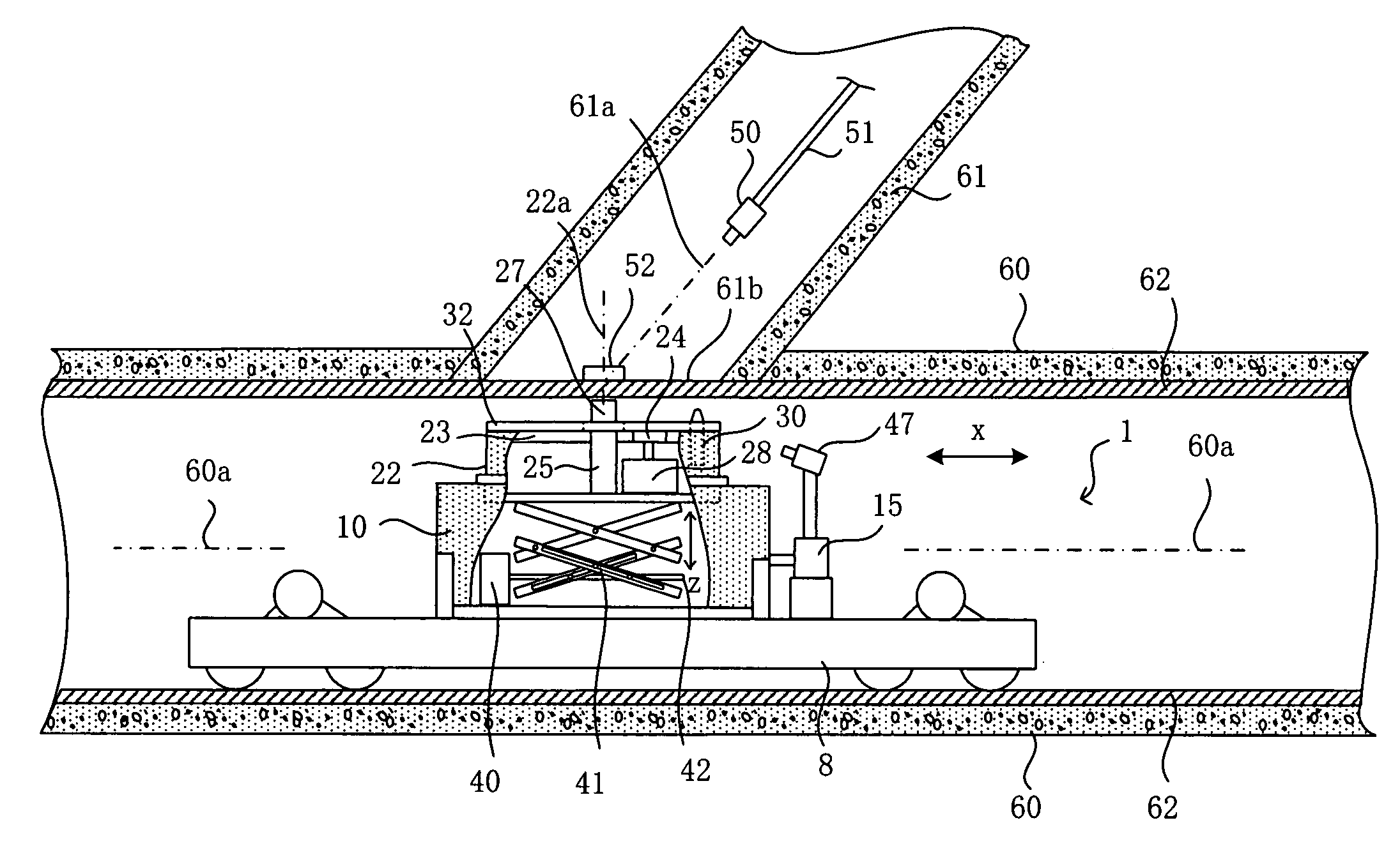
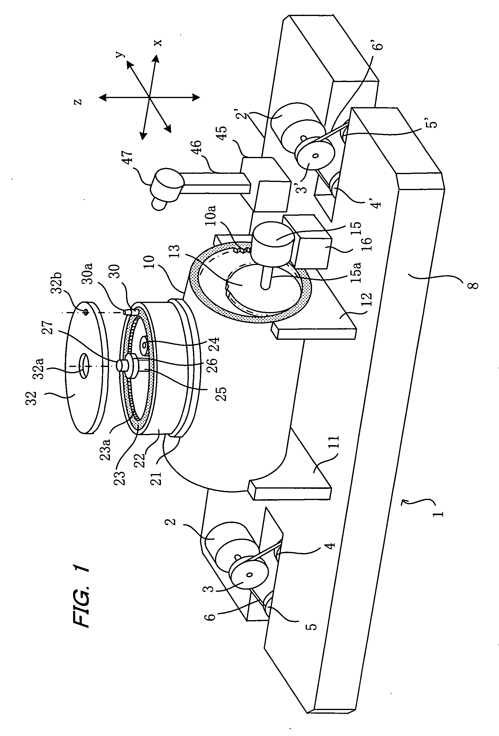
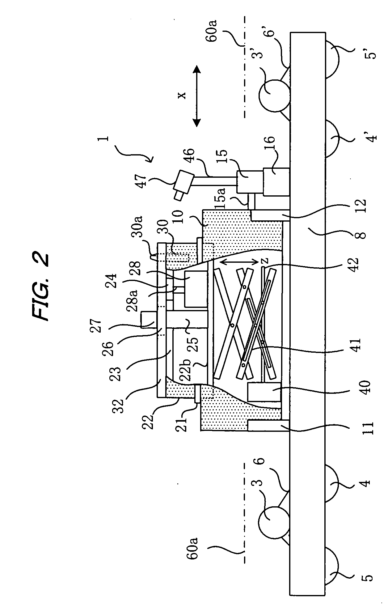
[0031]The present invention will now be described in detail based on the illustrated embodiments. The embodiments are described with reference to a case in which a sewer pipe or other main pipe is used as the first pipe, and a lateral pipe which branches from the main pipe to aboveground is used as the second pipe. However, the present invention is not limited to these embodiments alone and can be applied to a system for drilling a hole in an arrangement in which the first and second pipes intersect with each other, and an opening that communicates with the second pipe is formed at the intersection. An embodiment will be described in which the first pipe is lined with a pipe lining material, a hole is formed in the lined first pipe to provide an opening. However, the method can also be applied to a pipe that has not been lined. The present invention can also be applied to a case of forming a hole in that lining material portion of a main pipe that blocks the open end of a lateral pi...


PUM

PropertyMeasurementUnit
velocityaaaaaaaaaa
diameteraaaaaaaaaa
pressureaaaaaaaaaa

Abstract

A main pipe is lined using a pipe lining material that blocks the opening of a lateral pipe branching from the main pipe. An in-pipe work robot is provided with a cutting nozzle for spraying a pressurized fluid material or pressurized granular material onto the pipe lining material of the main pipe. The cutting nozzle is moved to a predetermined position inside the main pipe and rotated about a vertical axis by a rotary mechanism to cut the lining material between the first and second pipes by the pressurized fluid material or pressurized granular material sprayed from the cutting nozzle in order to form an opening for communicating the main pipe with the lateral pipe. The cutting nozzle can be moved in desired positions to drill holes accurately without damaging the internal peripheral surface of the lateral pipe.

Description

BACKGROUND OF THE INVENTION[0001]1. Field of the Invention[0002]The present invention relates to an in-pipe work robot, and more specifically to an in-pipe work robot for performing pipe work inside a first pipe (sewer main pipe) intersecting with a second pipe (lateral pipe).[0003]2. Description of the Related Art[0004]When a sewer pipe or another existing pipe buried underground has deteriorated, it is known that a pipe lining method is used to line the existing pipe using a pipe lining material in order to restore the existing pipe without digging up the pipe. The pipe lining material is comprised of a flexible tubular resin absorbing material impregnated with an uncured liquid setting resin (commonly a thermosetting resin). The resin absorbing material is made of a non-woven fabric having a pipe shape corresponding to the shape of the existing pipe. A highly airtight plastic film is coated on the external peripheral surface of the resin absorbing material.[0005]In the lining wor...

Claims


Application Information

Patent Timeline
Patent Type & Authority Applications(United States)
IPC IPC(8): B23D21/14B08B9/00
CPCF16L55/265Y10T83/384Y10T83/364
Inventor TSUJISAMA, TAKAHIKOKAMIYAMA, TAKAOUENO, MASAO
Owner SHONAN GOSEI JUSHI SEISAKUSHO KK
Why Eureka
Try Eureka