Inline crankshaft journal

a technology of connecting rods and crankshafts, which is applied in the direction of connecting rods, bearings, shafts and bearings, etc., can solve the problems of requiring more parts and assembly time, and requiring more parts

Inactive Publication Date: 2009-09-10
CYCLONE POWER TECH
View PDF7 Cites 20 Cited by
  • Summary
  • Abstract
  • Description
  • Claims
  • Application Information

AI Technical Summary

Benefits of technology

[0008]The present invention is directed to an inline crankshaft journaling configuration that satisfies the need for opposing connecting rods that load the crankpin in a substantially coplanar manner. The crankshaft and connecting rod configuration for use in piston engines comprises a crankshaft having a separable crank throw wherein the separable crank throw includes a pair of laterally separated throw arms supporting a crankp

Problems solved by technology

Whether engines are of either single- or multi-cylinder design, the power strokes of the individual piston(s) impart a significant side load on the crankshaft.
This load is not constant but rather pulses in concert with the power strokes of the pistons thereby also inducing a cyclic and vibrational load to the crankshaft.
However, forked connecting rods are more expensive to fabricate and require more parts and

Method used


Image

  • Inline crankshaft journal
  • Inline crankshaft journal
  • Inline crankshaft journal

Examples


Embodiment Construction

[0017]For purposes of description herein, the terms “upper”, “lower”, “left”, “rear”, “right”, “front”, “vertical”, “horizontal”, and derivatives thereof shall relate to the invention as oriented in FIG. 1. However, one will understand that the invention may assume various alternative orientations and step sequences, except where expressly specified to the contrary. While the present invention has been shown and described in accordance with preferred and practical embodiments thereof, one will also recognize that departures from the instant disclosure are fully contemplated within the spirit and scope of the invention. Hence, specific dimensions and other physical characteristics relating to the embodiments disclosed herein are not to be considered as limiting, unless the claims expressly state otherwise.

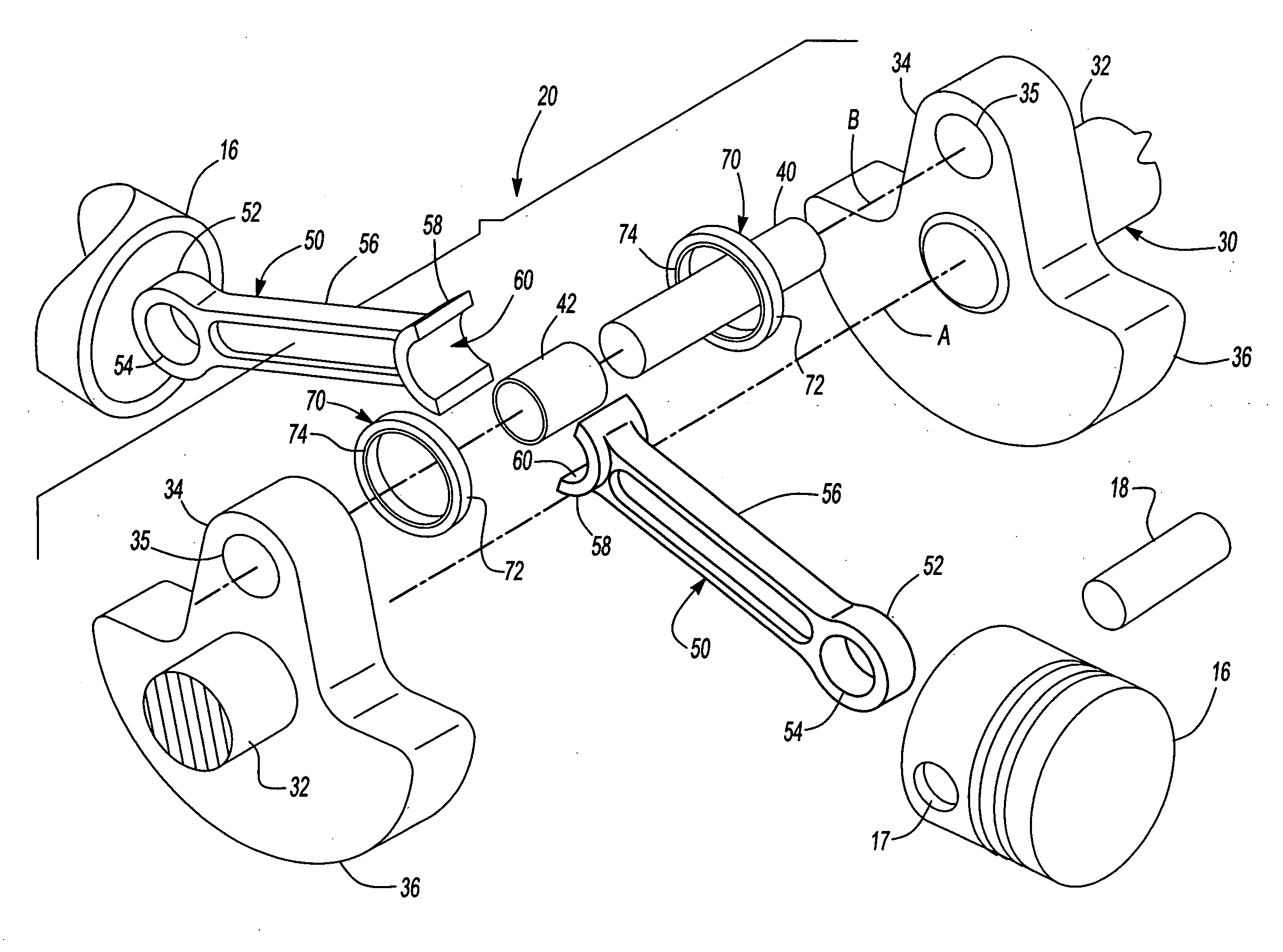
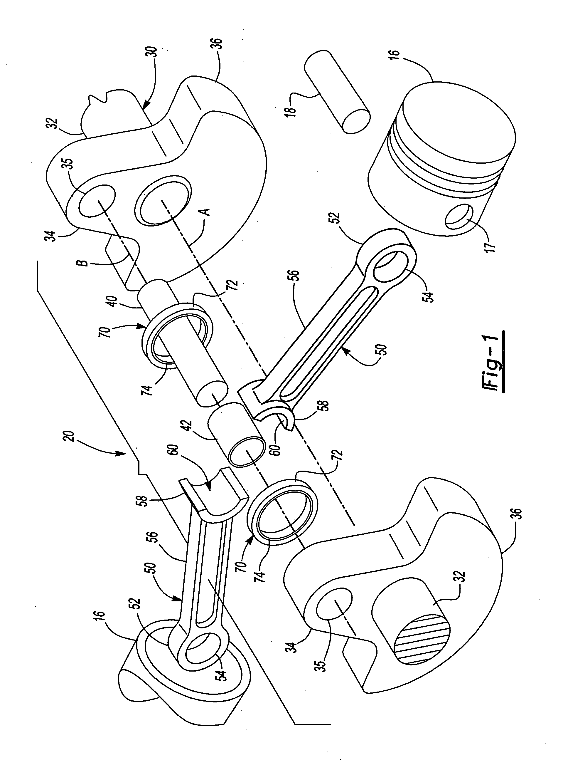
[0018]Turning to the drawings, FIG. 1 shows a combined crankshaft and connecting rod configuration 20 which is one of the preferred embodiments of the present invention and illustra...


PUM


Abstract

A crankshaft and connecting rod configuration for use in piston engines comprises a crankshaft having a separable crank throw wherein the separable crank throw includes a pair of laterally separated throw arms supporting a crankpin therebetween. A pair of coplanar connecting rods is in rotational engagement with the crankpin. Each rod has a small end configured for rotational attachment to a piston and a large end configured for the rotational engagement with the crankpin. At least one retention ring engages a portion of the large end of each connecting rod for maintaining the large ends of the connecting rods in rotational engagement with the crankpin.

Description

BACKGROUND OF THE INVENTION[0001]1. Field of the Invention[0002]The present invention relates to the journaling of piston connecting rods to crankshafts in general and more particularly to the inline journaling of two connecting rods to a single crankpin of a crankshaft.[0003]2. Discussion of the Related Art[0004]Engines have become a common element in industry and in everyday lives to provide power for operating a wide range of machinery. The most common of these engines are steam and internal combustion piston driven engines. In its simplest form, a piston driven engine comprises one or more pistons that are linearly driven within a substantially closed cylinder by a pressurized gas such as steam or post-combustion gasses. The piston is rotatably connected with one end of a connecting rod with the opposite end of the connecting rod being rotatably connected to a crank throw on a crankshaft. Each crank throw has a crankpin whose axis is offset from that of the crankshaft. The end o...

Claims


Application Information

Patent Timeline
IPC IPC(8): F16C3/04
CPCF16C9/04
Inventor SCHOELL, HARRY
Owner CYCLONE POWER TECH
Why Eureka
Try Eureka