Cleaning apparatus, cleaning tank, cleaning method, and method for manufacturing article

a technology of cleaning apparatus and cleaning tank, which is applied in the direction of cleaning process and apparatus, cleaning using liquids, chemistry apparatus and processes, etc., can solve the problem of drying the whole article to be cleaned, and the effect of poor efficiency

Inactive Publication Date: 2009-09-10
FUJITSU LTD +1
View PDF1 Cites 10 Cited by
  • Summary
  • Abstract
  • Description
  • Claims
  • Application Information

AI Technical Summary

Benefits of technology

[0027]Further, the cleaning apparatus and the cleaning tank circulate drying fluid in the cleaning tank, jet or suck the drying fluid through the opening, and dry the cleaning fluid on the area to be cleaned of the article to be cleaned. Thus, according to the cleaning apparatus and the cleaning tank, it is possible to selectively dry the area to be cleaned corresponding to the opening. As a result, the article to be cleaned can be dried for a short time.

Problems solved by technology

However, the conventional cleaning apparatus described with reference to FIG. 12 has a problem that the foreign matters 100 close to the article to be cleaned 1 or at a corner of the cleaning tank 10 stays not to be discharged so that the foreign matters 100 in the cleaning fluid adhere to the article to be cleaned 1 when the article to be cleaned 1 is taken out of the cleaning tank 10.
Thus, drying the whole article to be cleaned 1 takes longer to have poor efficiency.
Further, as shown in FIG. 13, there is a problem that the foreign matters 100 adhere to the article to be cleaned 1, when the cleaned article to be cleaned 1 is taken out of the cleaning tank 10 for being transferred to a drying apparatus.

Method used


Image

  • Cleaning apparatus, cleaning tank, cleaning method, and method for manufacturing article
  • Cleaning apparatus, cleaning tank, cleaning method, and method for manufacturing article
  • Cleaning apparatus, cleaning tank, cleaning method, and method for manufacturing article

Examples


Embodiment Construction

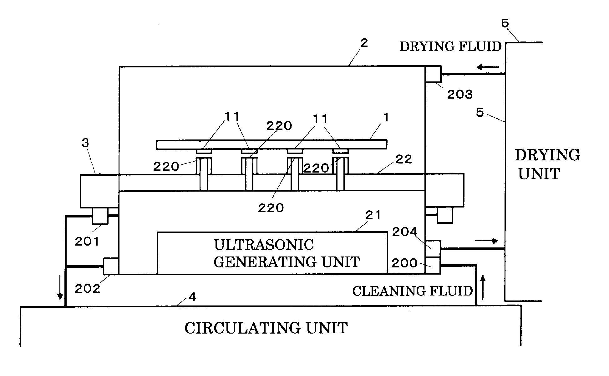
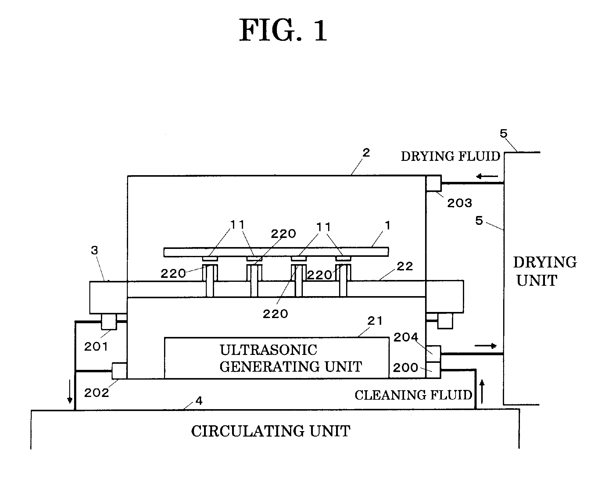
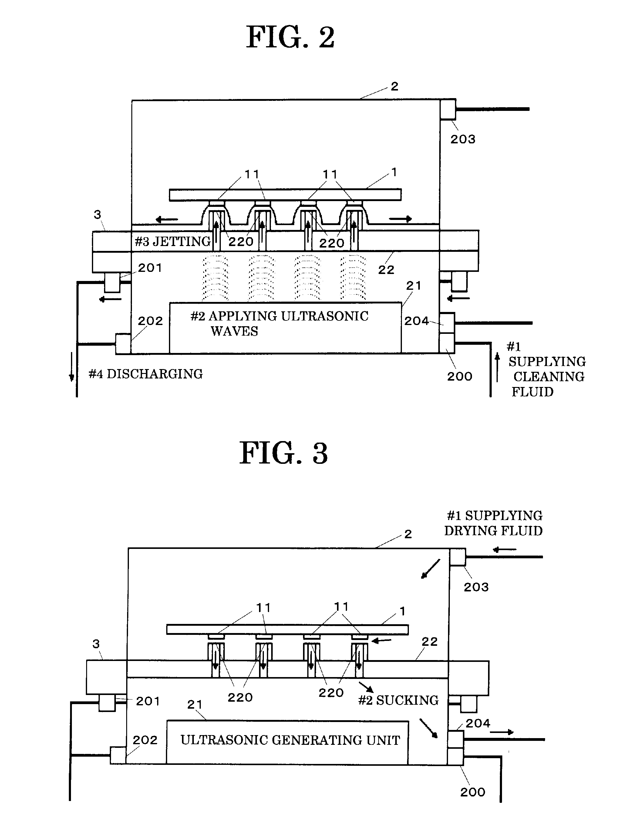
[0039]Hereinafter, an embodiment of the present invention is described with drawings. FIG. 1 is a diagram showing an exemplary basic structure of a cleaning apparatus of the present embodiment. The cleaning apparatus shown in FIG. 1 places an article to be cleaned 1 in a cleaning tank 2 and removes foreign matters on a surface of the article to be cleaned by using cleaning fluid. Among components of the cleaning apparatus shown in FIG. 1, the cleaning tank 2 has a supply port 200 for supplying the cleaning fluid and an outlet 202 for discharging the cleaning fluid, and stores the cleaning fluid. The cleaning fluid is, for example, pure water, an organic solvent and so on.

[0040]The cleaning tank 2 includes an ultrasonic generating unit 21 and a fluid jetting unit 22. The ultrasonic generating unit 21 is provided opposing the fluid jetting unit 22. The ultrasonic generating unit 21 has one ultrasonic oscillator or more. The ultrasonic generating unit 21 applies ultrasonic waves to the...


PUM


Abstract

Ultrasonic generating unit of a cleaning tank in a cleaning apparatus applies ultrasonic waves to cleaning fluid supplied into the cleaning tank from a supply port and fluid jetting unit having openings at locations corresponding to areas to be cleaned of an article to be cleaned jets the ultrasonic-applied cleaning fluid from the openings to the areas to be cleaned of the article to be cleaned.

Description

CROSS-REFERENCE TO RELATED APPLICATIONS[0001]This application claims the conventional priority based on Japanese Application No. 2008-059071, filed on Mar. 10, 2008, the disclosures of which are incorporated herein by reference.BACKGROUND OF THE INVENTION[0002]1. Field of the Invention[0003]The present invention relates to a cleaning apparatus, a cleaning tank, a cleaning method and a method for manufacturing an article only cleaning an area to be cleaned of an article to be cleaned. The present invention relates to a cleaning technique in a manufacturing process of a small device, for example, a magnetic head of a HDD (Hard Disk Drive), a MEMS (Micro Electro Mechanical Systems) and an optical component (a mirror, a lens and so on).[0004]2. Description of the Related Art[0005]Recently, it is necessary to remove submicron foreign matters generated in manufacturing processes by precisely cleaning according to achieving higher accuracy and downsizing in small devices such as magnetic h...

Claims


Application Information

Patent Timeline
Patent Type & Authority Applications(United States)
IPC IPC(8): B08B3/12
CPCB08B3/02B08B2203/0288B08B3/12B08B3/10
Inventor NOMURA, MICHINAOYANAGIDA, YOSHIAKIKOBAYASHI, SHUSUKE
Owner FUJITSU LTD
Why Eureka
Try Eureka