Water flow control device

a technology of water flow control and control device, which is applied in the direction of valve housing, manufacturing tools, machines/engines, etc., can solve the problems of large water damage, many prior art devices do not provide an area on the handle or lever to apply text or graphics, and the water line between the main valve and the water flow control device could be left in a pressurized condition for potentially a long time, etc., to achieve easy and cost-effective manufacturing and easy mounting

Inactive Publication Date: 2009-09-10
BAUTCH PHILLIP
View PDF10 Cites 4 Cited by
  • Summary
  • Abstract
  • Description
  • Claims
  • Application Information

AI Technical Summary

Benefits of technology

[0008]Accordingly, it is an object of this invention to provide an improved water flow control device that can be easily and cost-efficiently manufactured and that is easily mount

Problems solved by technology

However, all prior art water flow control devices leave the orientation of their levers or handles in relation to the user to chance.
If a user inadvertently forgets to also shut of the main valves, the water line between the main valves and the water flow control device could be left in a pressurized condition for potentially a long period of time.
However, typical water supply lines are not intended to be left in a pressurized condition for any period of time and there is a strong possibility that leaks in the supply line may deve

Method used


Image

  • Water flow control device
  • Water flow control device
  • Water flow control device

Examples


Embodiment Construction

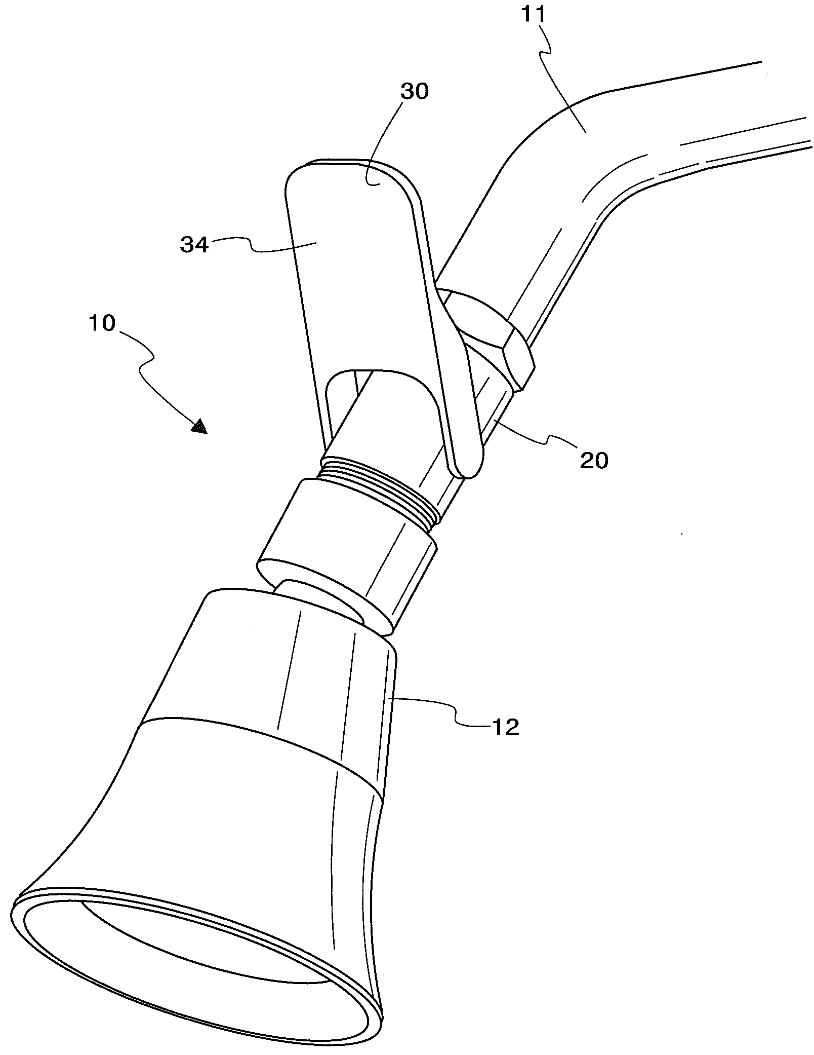
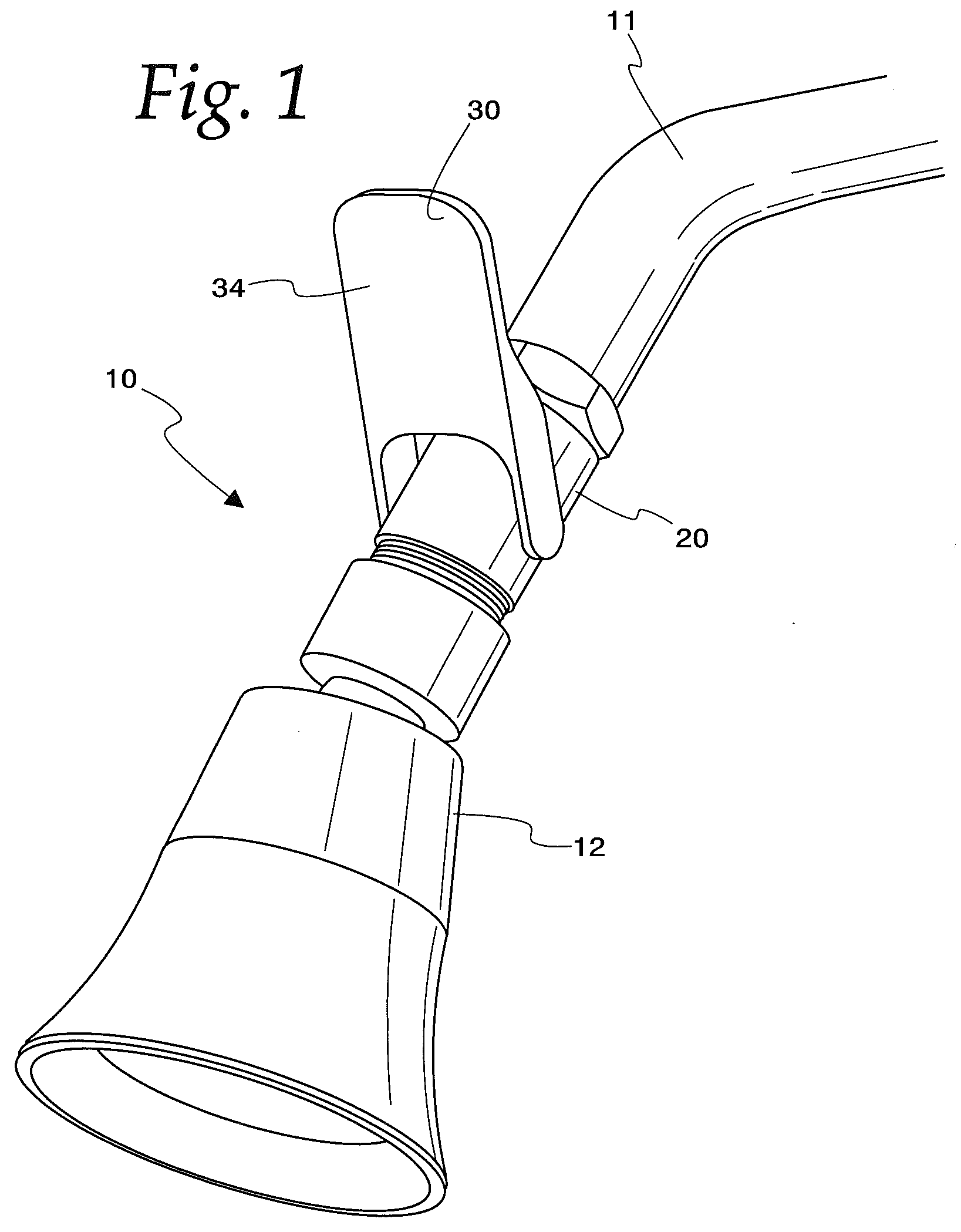
[0031]Turning now to the Figures, FIG. 1 is illustrative of a preferred water flow control device assembly 20 to control the amount of water flowing through the device incorporating the features of the present invention. In particular, it shows water flow control device 20 fully assembled and installed as part of shower system 10, whereby water flow control device 20, having a handle member 30 and a display area 34 is mounted between water supply line 11 and shower head 12.

A. The Components of the Water Flow Control Device

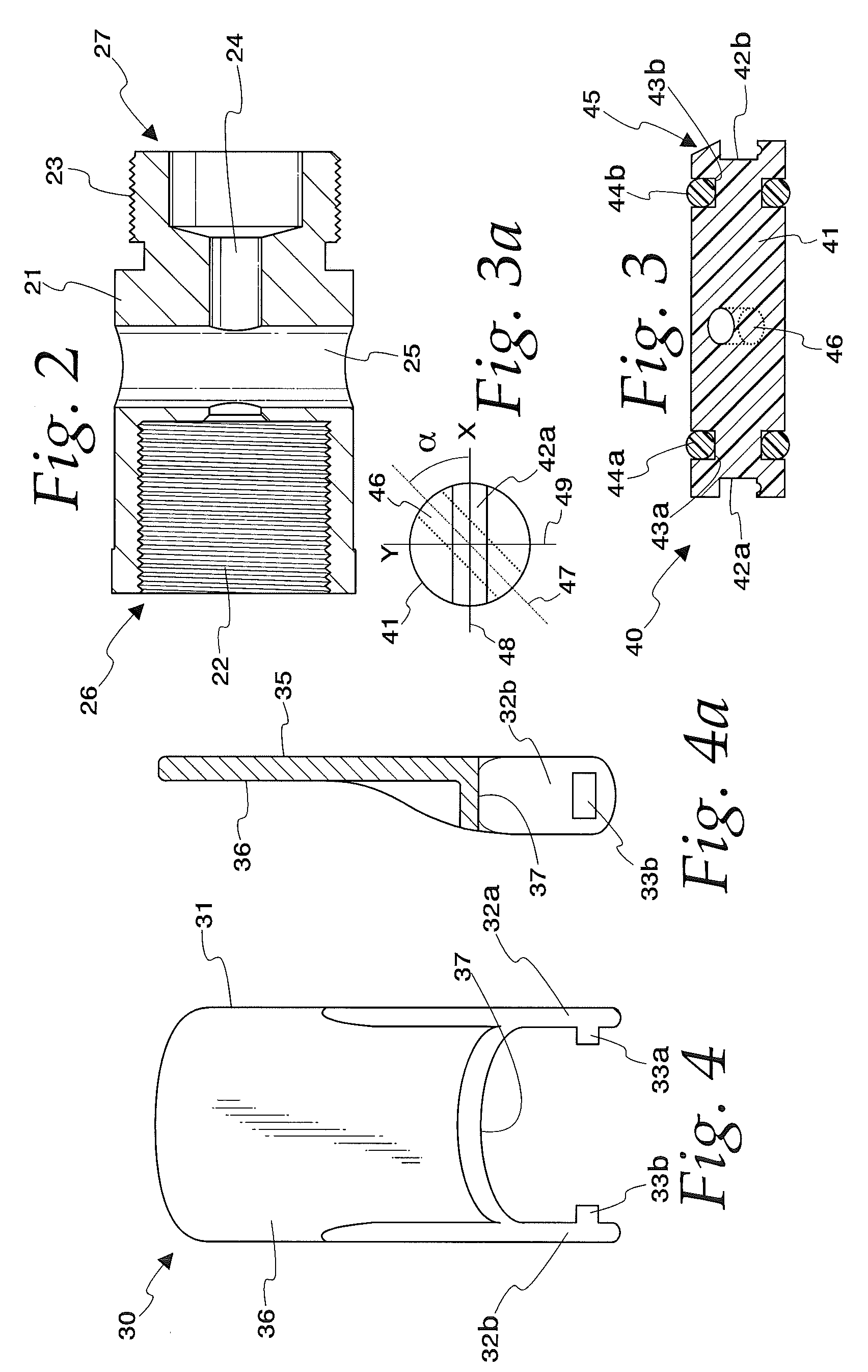
[0032]FIGS. 2 through 4a show in detail the three components of the disclosed water flow control device 20, that is, a housing, a valve member, and a handle member. Turning first to FIG. 2, FIG. 2 shows a cross-sectional view of a preferred embodiment of housing 21 having on one side an input end 26 through which, when connected to a water supply line, water will flow into the device, and on the opposite side, an output end 27 through which water will flow out of t...


PUM

PropertyMeasurementUnit
Flow rateaaaaaaaaaa
Diameteraaaaaaaaaa
Areaaaaaaaaaaa

Abstract

A water flow control device for installation between a water supply line and a nozzle, shower head or the like, whereby the water flow control device comprises a handle member connected to a valve member for controlling the flow of water between full flow and reduced flow, whereby the assembly and installation of the water flow control device ensures that the handle to control the water flow is oriented the same way for every installation.

Description

RELATED APPLICATION[0001]This application claims the benefit of U.S. Provisional Application No. 61 / 068,836, filed Mar. 10, 2008.FIELD OF THE INVENTION[0002]The present invention relates generally to an improved water flow control device and a method of installation thereof. More specifically, this invention relates to an improved water flow control device mounted between a water supply line and a nozzle enabling a user to regulate the amount of water flowing through the control device.DESCRIPTION OF THE PRIOR ART[0003]Water flow control devices, in particular for reducing the water flow in shower applications are known in the art and are used to help preserve water and save energy related to heating the water. For example, U.S. Pat. No. 4,191,332 to De Langis et al. discloses a shower head flow control device comprising a push / pull rod type valve mechanism for on / off control of the water flow. U.S. Pat. No. 5,613,639 to Storm et al. discloses an on / off control valve for showers usi...

Claims


Application Information

Patent Timeline
IPC IPC(8): F15C4/00B23P11/00
CPCB05B1/3026Y10T29/49826F16K27/065F16K5/0442Y10T137/8593
Inventor BAUTCH, PHILLIP
Owner BAUTCH PHILLIP
Why Eureka
Try Eureka