Automated floor board texturing cell and method

a floor covering and texturing technology, applied in the field of texturing floor coverings, can solve the problems of increasing the cost of the floor covering, lack of control and expertise, and laborious hand texturing

Active Publication Date: 2009-09-10
ALADDIN MFG CORP
View PDF28 Cites 19 Cited by
  • Summary
  • Abstract
  • Description
  • Claims
  • Application Information

AI Technical Summary

Benefits of technology

The patent describes a machine for texturing floor boards. The machine has a base or a gantry that supports a moveable arm or bridge, with a tool mounted on it. The machine has a support member to hold the floor board in a fixed position while the tool applies a texturing pattern to the floor board. The machine allows for changing the orientation of the tool with respect to the floor board surface without interrupting the texturing operation. The technical effect of the patent is to provide a machine that allows for efficient and precise texturing of floor boards.

Problems solved by technology

The technical problem addressed in this patent text is the shortcomings of conventional texturing techniques and machines used for creating unique floor boards with richness and antique looks. Hand-texturing can be labor-intensive, costly, and results can vary based on the artisan's skill and the condition of the floor board. Conventional machine-texturing can result in pattern repetition and unacceptable variations in appearance, and it is difficult to economically texture floor boards with various dimensions.

Method used


Image

  • Automated floor board texturing cell and method
  • Automated floor board texturing cell and method
  • Automated floor board texturing cell and method

Examples


Embodiment Construction

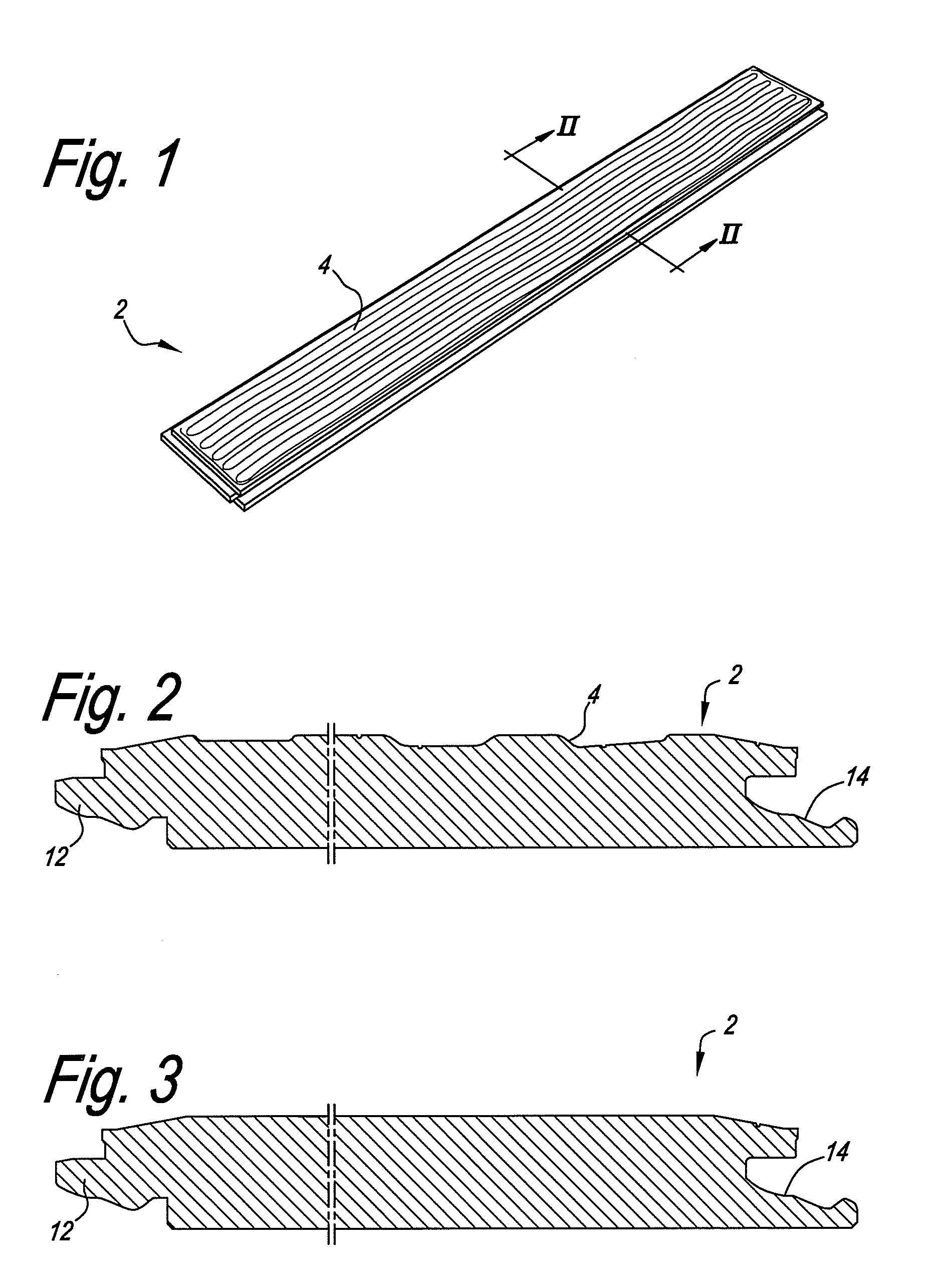
[0017]With reference to FIG. 1, an example floor board 2 includes a pair of opposed major surfaces, i.e., the larger upward and the larger downward facing surfaces. The opposed major surfaces are generally planar and generally rectangular shaped. A pair of long side surfaces and a pair of short side surfaces extend between the opposed major surfaces.

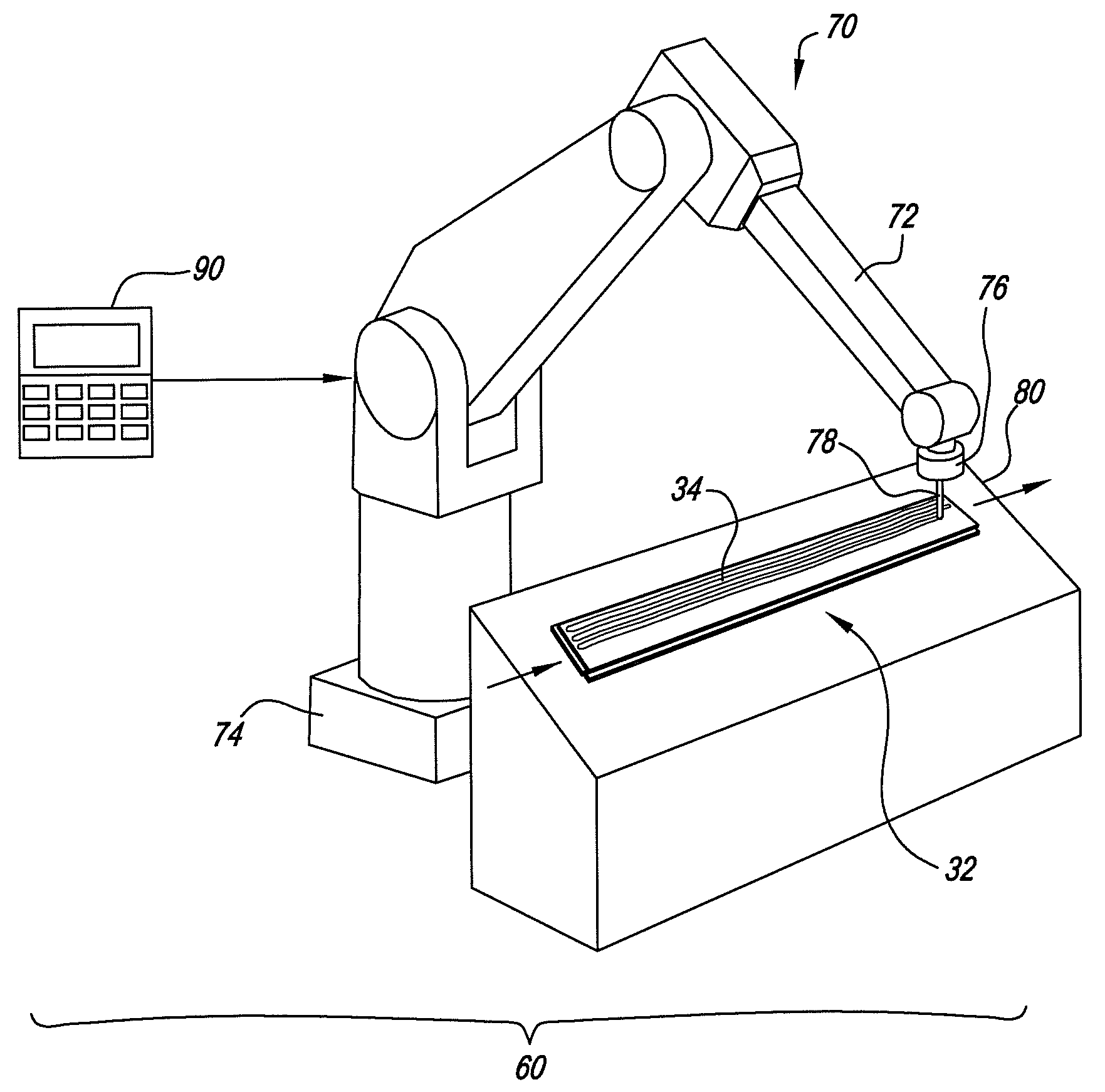
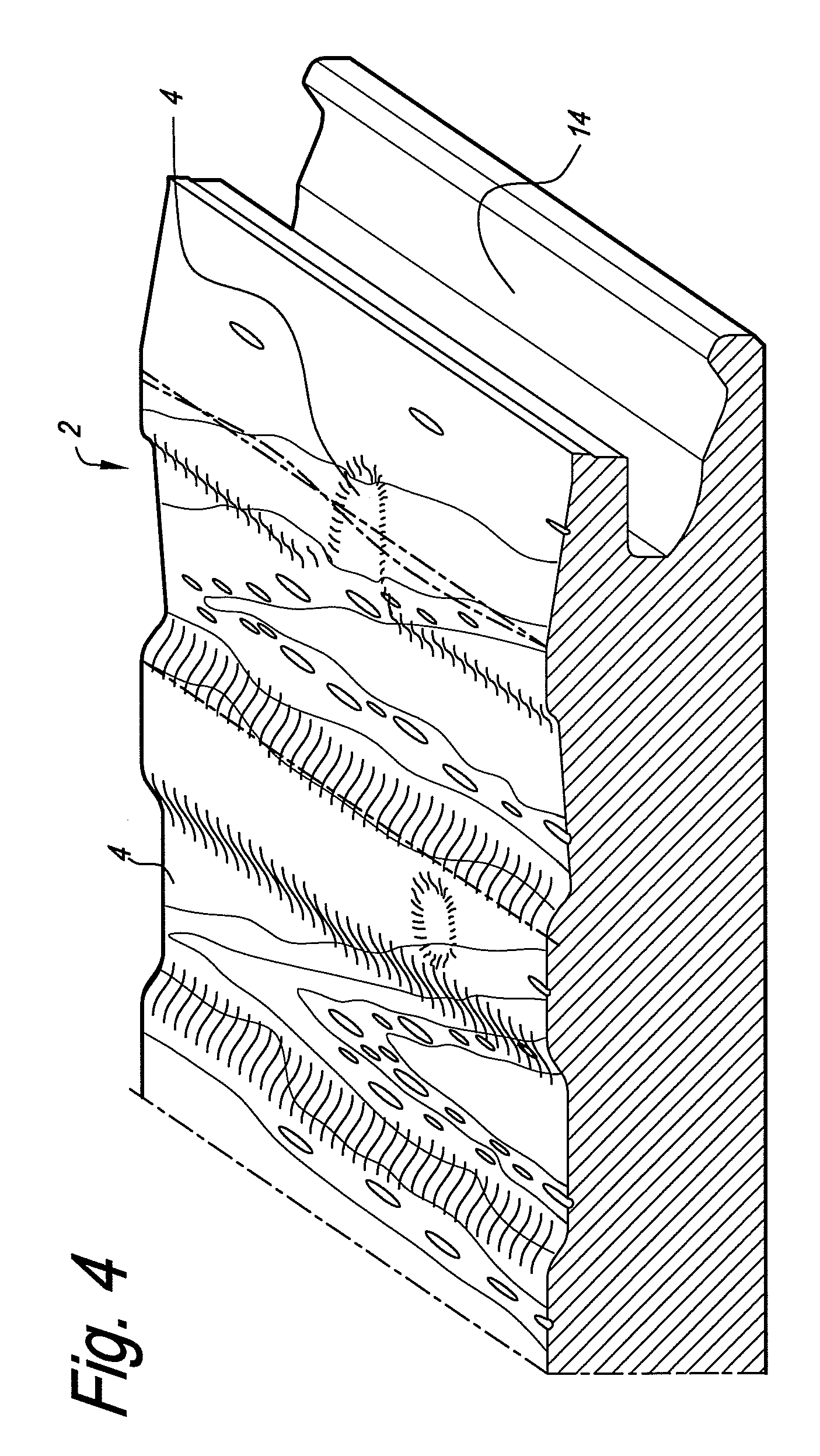
[0018]The upper major surface includes texture marks 4. In this example embodiment, the texture marks 4 are provided by an automated texturing operation as discussed in more detail below. In alternative embodiments, the texture marks may be provided by one or more automated operations including (but not limited to) scraping, denting, brushing, sanding, roughening, burning, sawing and / or routing. According to the present example, the texture marks 4 are essentially provided in the longitudinal direction of the floor board, i.e., essentially parallel to the long side surfaces. Substantially the entire upper major surface of the floor board...


PUM


Abstract

An automated floor board texturing cell includes a programmable robot that stores, or has access to, a plurality of patterns. The robot automatically selects a stored pattern for at least one of the floor boards introduced into the cell. The robot textures the floor boards to exhibit the selected pattern. The robot may select a pattern for a batch of floor boards or for each individual floor board. Pattern selection can be random or based on stored information such as a production schedule.

Description


Claims


Application Information

Patent Timeline
Owner ALADDIN MFG CORP
Why Eureka
Try Eureka