Well treatment using a progressive cavity pump

a technology of progressive cavity and well treatment, which is applied in the direction of positive displacement liquid engine, borehole/well accessories, liquid fuel engine, etc., can solve the problems of high cost of truck-mounted pumping units to treat formation, significant fees for renting pumping units, and high cost of truck-mounted pumping units

a technology of progressive cavity and well treatment, which is applied in the direction of positive displacement liquid engine, borehole/well accessories, liquid fuel engine, etc., can solve the problems of high cost of truck-mounted pumping units to treat formation, significant fees for renting pumping units, and high cost of truck-mounted pumping units

US20090223665A1Inactive Publication Date: 2009-09-10WEATHERFORD TECH HLDG LLC

Image

  • Well treatment using a progressive cavity pump
  • Well treatment using a progressive cavity pump
  • Well treatment using a progressive cavity pump

Examples


Embodiment Construction

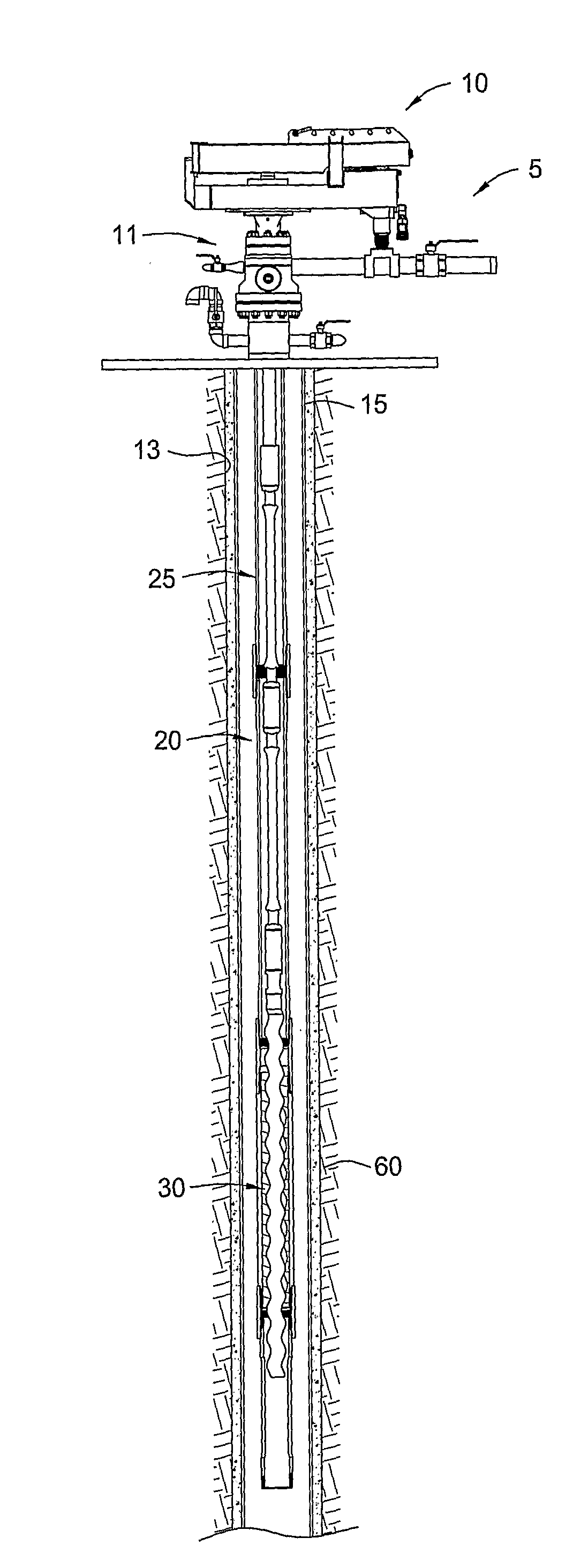
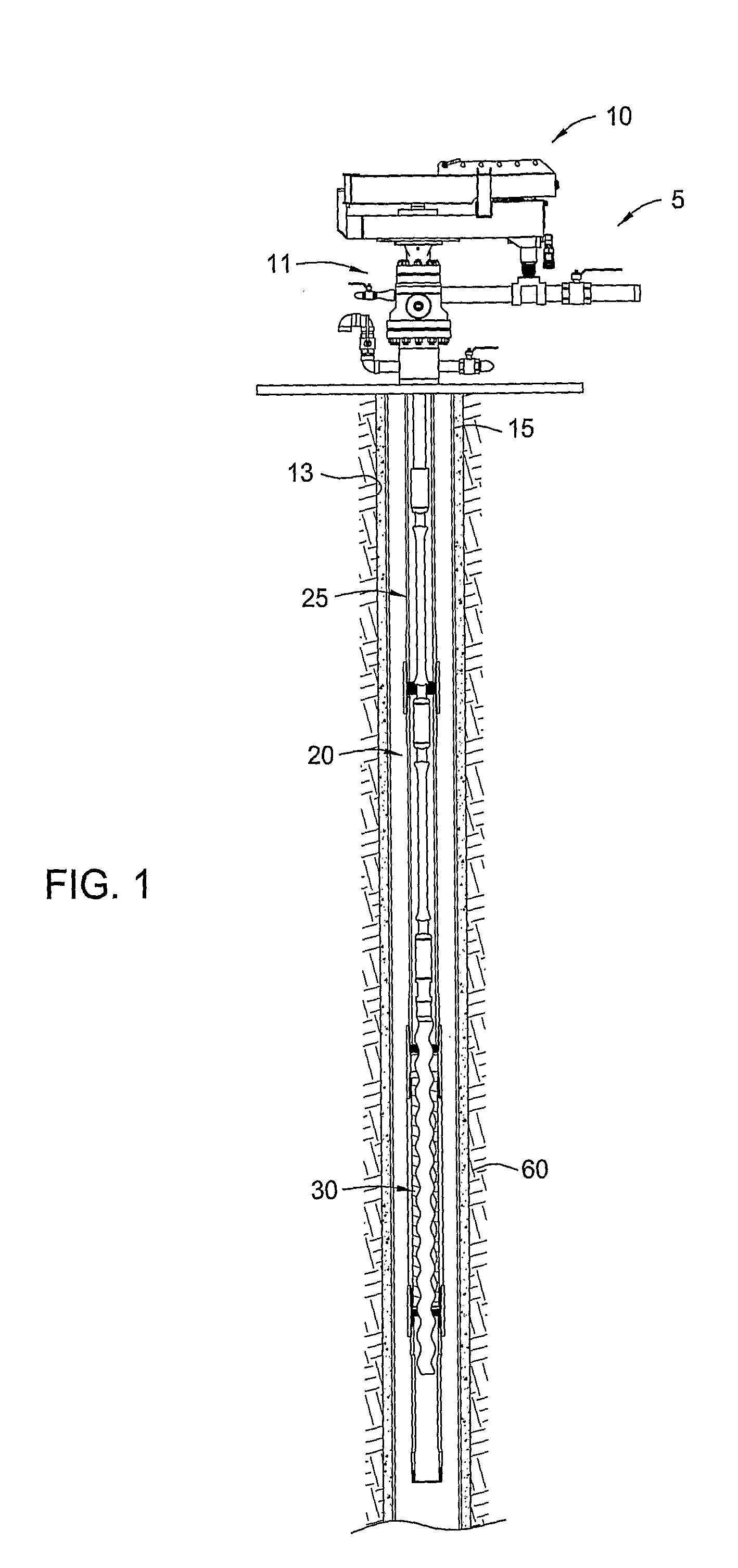
[0024]FIG. 1 shows a PCP lift system, which includes a PCP 30 powered by one or more drive mechanisms 10. A valve system 5 of the drive mechanism 10 regulates fluid flow through the PCP 30. The drive mechanism 10 generally includes a motor, such as a hydraulic motor, for providing torque and rotation to a drive string or rod string 25 (also termed “sucker rod”) disposed within the drive mechanism 10. The drive string 25 operatively connects the PCP 30 to the motor of the drive mechanism 10.

[0025]A wellbore 13 extends into an earth formation 60 below the drive mechanism 10. Casing 15 is preferably set within the wellbore 13 using cement or some other physically alterable bonding material. (In the alternative, the wellbore 13 may be only partially cased or may be an open hole wellbore.) Preferably, the casing 15 extends from a wellhead 11, which provides a sealed environment for the PCP 30. The wellhead 11 comprises high and low pressure rams to manage the pressure of the fluid within...


PUM


Abstract

Embodiments of the present invention include methods and apparatus for treating a formation with fluid using a downhole progressive cavity pump (“PCP”). In one aspect, the direction of the PCP is reversible to pump treatment fluid into the formation. In another aspect, two or more PCP's are disposed downhole and reversible to allow a chemical reaction downhole prior to the treatment fluid entering the formation. In yet another aspect, embodiments of the present invention provide a method of flowing treatment fluid downhole using one or more downhole PCP's. Treatment of the formation with the fluid and production of hydrocarbon fluid from the formation may both be conducted using the same downhole PCP operating in opposite rotational directions. In an alternate embodiment, one or more downhole PCP's may be utilized in tandem with one or more surface pumps.

Description

CROSS REFERENCE TO RELATED APPLICATION[0001]This application claims benefit of co-pending U.S. Provisional Patent Application Ser. No. 60 / 674,805, filed on Apr. 25, 2005, which application is herein incorporated by reference in its entirety.BACKGROUND OF THE INVENTION[0002]1. Field of the Invention[0003]Embodiments of the present invention generally relate to artificial fluid-lift mechanisms within a wellbore. More particularly, embodiments of the present invention relate to progressive cavity pumps within the wellbore.[0004]2. Description of the Related Art[0005]To obtain hydrocarbon fluids from an earth formation, a wellbore is drilled into the earth to intersect an area of interest within a formation. The wellbore may then be “completed” by inserting casing within the wellbore and setting the casing therein using cement. In the alternative, the wellbore may remain uncased (an “open hole wellbore”), or may become only partially cased. Regardless of the form of the wellbore, produc...

Claims


Application Information

Patent Timeline
10 Sep 2009
Publication
US20090223665A1
IPC
E21B43/12; E21B43/16; E21B43/267; E21B43/26; F04C2/107
CPC
E21B43/26; E21B43/126; E21B43/2607; F01C1/101; F04B47/00
Inventors
COLLEY, III, E. LEE