Rapid Cycling Press for Forming a Composite Article

Inactive Publication Date: 2009-09-10
MICARELLI JAMIN
View PDF13 Cites 15 Cited by
  • Summary
  • Abstract
  • Description
  • Claims
  • Application Information

AI Technical Summary

Benefits of technology

[0032]Once this phase of increasing pressure has ‘set’ the gasket, the pressure is further increased to operational range, with each increment of pressure serving to further pressurize and hold the angled member against its sealing surface via the pressure transfer laterally through the silicone in the gasket to the angled member. Such gaskets desirably have a corner-free, or rounded, or U-shaped cross-section at the junction of the outer (or inner) member and the angled member. When the pressure in the chamber is reduced, and the corresponding pressure holding the angled member against its respective sealing or mating surface is released, the angled member springs back to its un-pressured configuration and dimension (permitted by the silicone's resilience), and the gasket ceases to be an interference fit, and the chamber lid or door is thus readily opened.
[0033]Also disclosed is a rapidly heating and cooling dual-purpose platen. The dual design includes a hot platen member (defined as a platen that has a heating system integrated, either fluid or electrical) and a cold platen member. The two platen members a

Problems solved by technology

But autoclaves are expensive and limited in pressure range and vacuum bag

Method used


Image

  • Rapid Cycling Press for Forming a Composite Article
  • Rapid Cycling Press for Forming a Composite Article
  • Rapid Cycling Press for Forming a Composite Article

Examples


Embodiment Construction

[0046]Turning now to the drawings, the disclosed press and method are described in illustrative embodiments by reference to the numerals of the drawing figures wherein like numbers indicate like parts.

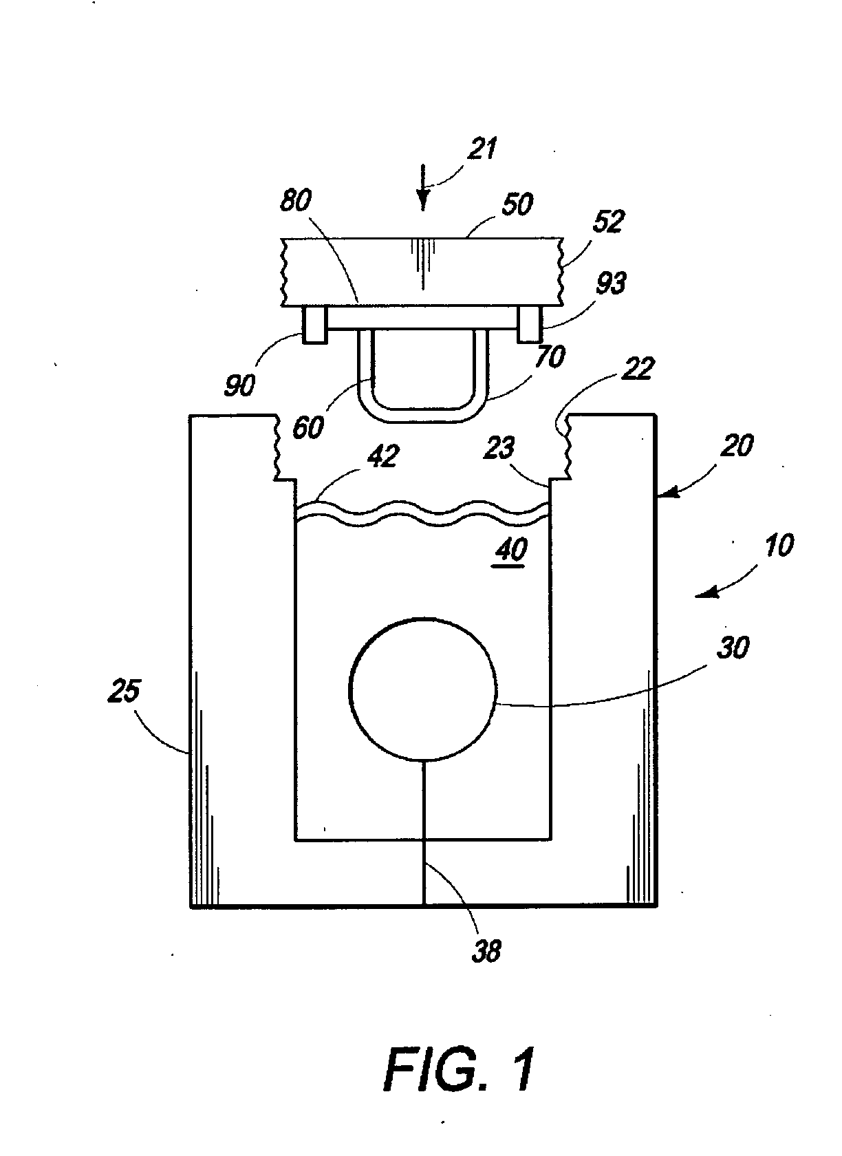
[0047]FIGS. 1 and 4 schematically illustrate an example of the disclosed press. The arrows inside vessel 30 schematically and graphically illustrate increasing pressure as the fluid 35 is pumped into vessel 30 via conduit 38 from a high pressure source of the fluid (not shown). The increasing number of such arrows from FIG. 4a in sequence to FIG. 4d is a kind of graphic schematic scale to illustrate that as fluid is pumped into vessel 30, and the fluid pressure goes up, the work piece or formable part 70 is subject to greater and greater pressure through the pressure transfer medium 40.

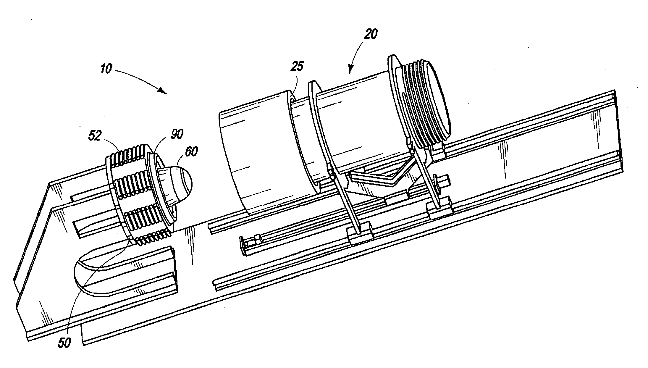
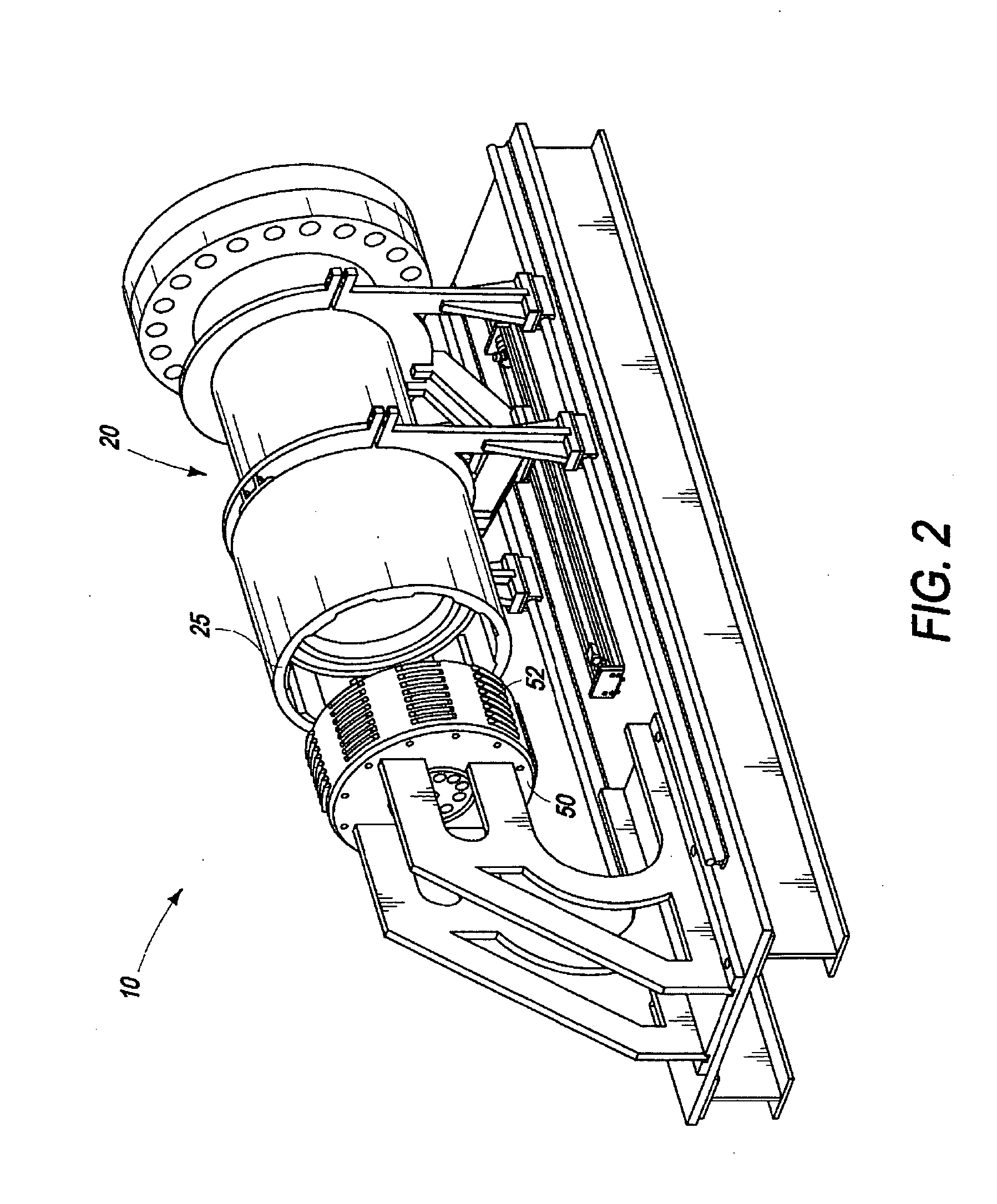
[0048]FIGS. 2 and 3 are alternate perspective views of an embodiment of the disclosed press showing particular features such as artillery breach threading 52. One configuration of pressure chamber 20 has...


PUM

PropertyMeasurementUnit
Pressureaaaaaaaaaa
Pressureaaaaaaaaaa
Pressureaaaaaaaaaa

Abstract

A press includes a pressure chamber filled with a substantially incompressible medium that at least partially encloses an elastomeric vessel filled with a substantially incompressible fluid that is in fluid communication with a pressurized source of the same fluid. Method and systems employing the press are also disclosed.

Description

[0001]This application claims priority to U.S. Provisional Application 61 / 068,964 filed Mar. 10, 2008.TECHNICAL FIELD[0002]The invention relates to the field of presses and molding; particularly, it relates to method and apparatus for a forming a high strength composite article; more particularly, it relates to a rapidly cycling pressure chamber filled with a pressure transfer medium such as silicone that encloses a high pressure elastomeric vessel.BACKGROUND OF THE INVENTION[0003]In a conventional hydraulic press there is a steel piston chamber that contains oil and as oil is pumped into the piston chamber, the piston is pushed out of the piston chamber into pressurized contact with a work piece. In an alternate, or hydro-forming press, high-pressure water is forced into a closed chamber against a metal sheet or tube and, as the pressure builds in the chamber, the sheet is pressed and stretched into a cavity behind it. Another press positions a work piece between a conventional mov...

Claims


Application Information

Patent Timeline
IPC IPC(8): B29C43/18
CPCB29C43/10B29C43/36B29C43/3642B29C2043/106B30B5/02B29C2043/3615B29C2043/366B29C2043/5808B29C2043/3238
Inventor MICARELLI, JAMIN
Owner MICARELLI JAMIN
Why Eureka
Try Eureka