
Method for configuring a node of an industrial wireless network

Active Publication Date: 2009-09-10
ABB (SCHWEIZ) AG
View PDF12 Cites 74 Cited by
  • Summary
  • Abstract
  • Description
  • Claims
  • Application Information

AI Technical Summary

Benefits of technology

[0020]The wireless technology used to communicate information required for a specific wireless node of the field device to join a known or first wireless network may be a wireless radio technology. A preferred technology is a spread spectrum technology using for example an Industrial Scientific and Medical (ISM) band. Such a spread spectrum technology may use any suitable wireless protocol or standard such as any from the group of Wireless Local Area Network (WLAN), WirelessHART, ZigBee, Bluetooth, or a protocol developed by ABB called Wireless interface for sensors and actuators (WISA). In an advantageous embodiment the wireless radio technology allows multiple networks to operate in the same radio space without the risk of sharing data or misrouting messages. This can be done by including a network identity in every message. This network identity is used to bind nodes together into a network. If a node hears a node with a network identity that does not match its own, then it will not initiate joining. The network identity may be information of a similar type to a Service Set Identifier (SSID) used by a node to identify a wireless LAN (Local Area Network) for an 802.11 network. The network identity of a node can be changed by configuration. The same radio hardware and software may be used by the wireless node of the new field device to communicate, using one network identity, in one network with a wireless configuration device, as well as to communicate, using another network identity, in another network with the existing first wireless network. This makes configuration of a new field device with a wireless radio technology, or configuration of a field device which has been re-set, or moved, or where a part has been replaced, a quicker and more flexible operation even in a hazardous environment. Similarly the wireless configuration device may use the same radio hardware and software to communicate using one network identity with a new wireless node and using another network identity with the existing first wireless network.

Problems solved by technology

This makes it impossible to use the wireless network when downloading the initial configuration settings to the field device.
And if the field device is located in a hazardous environment there are requirements that the field device must be physically encapsulated, which makes it difficult to carry out the initial configuration using a direct wire connection between a handheld and the field device.

Method used


Image

  • Method for configuring a node of an industrial wireless network
  • Method for configuring a node of an industrial wireless network
  • Method for configuring a node of an industrial wireless network

Examples


Embodiment Construction

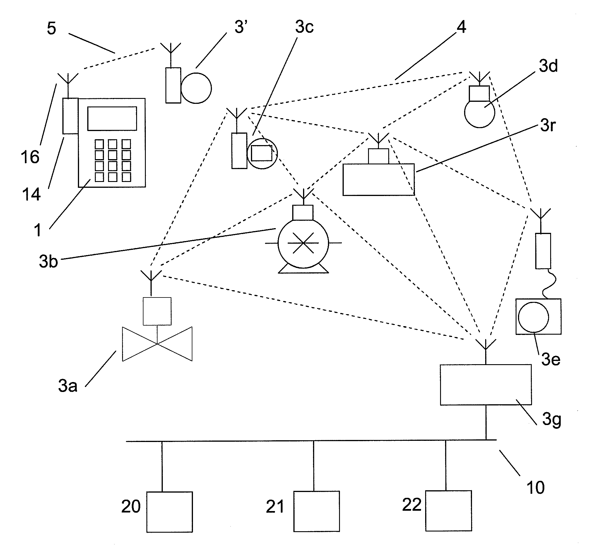
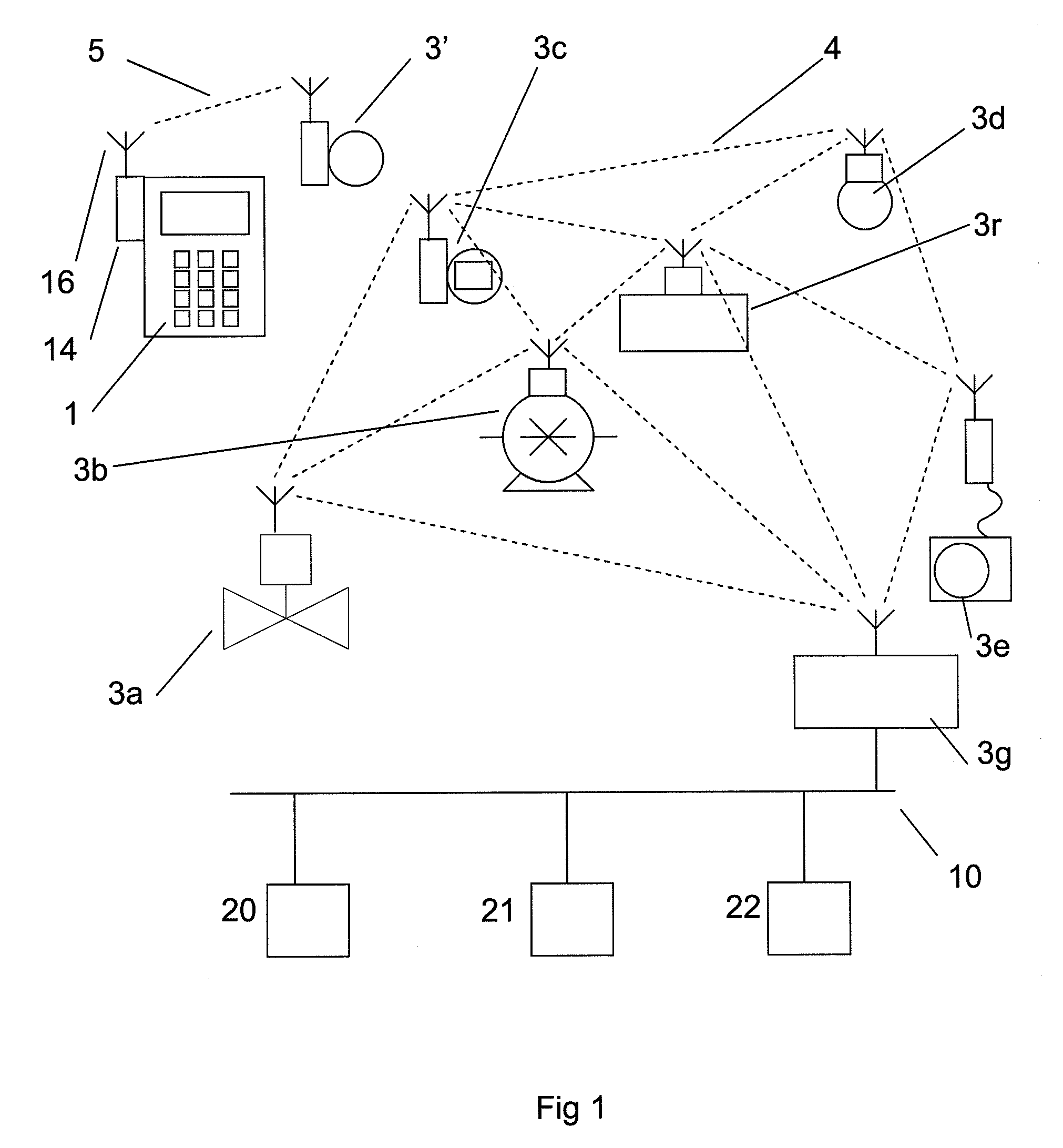
[0031]This invention describes communication and configuration using a wireless configuration device, and a method and system in which the device is employed. FIG. 1 shows a first wireless network 4 connected to a data network 10 of an industrial monitoring or control system (not shown). The first wireless network 4 is shown with 7 nodes 3a-n connected to it. Nodes 3a-e are field devices, being measuring instruments or sensors 3c-e, or else actuators such as motorised valve 3a and pump 3b. Wireless network 4 also has a node 3g which is a gateway of some sort into the data network 10. Node 3r is a router in the first wireless network 4. Also indicated in the diagram is a new field device 3′ which is not connected to the first wireless network 4. A wireless configuration device 1 is shown arranged with wireless hardware 14, 16. The wireless configuration device may be a handheld wireless device. The industrial monitoring or control system is symbolically shown to comprise a computer 2...


PUM


Abstract

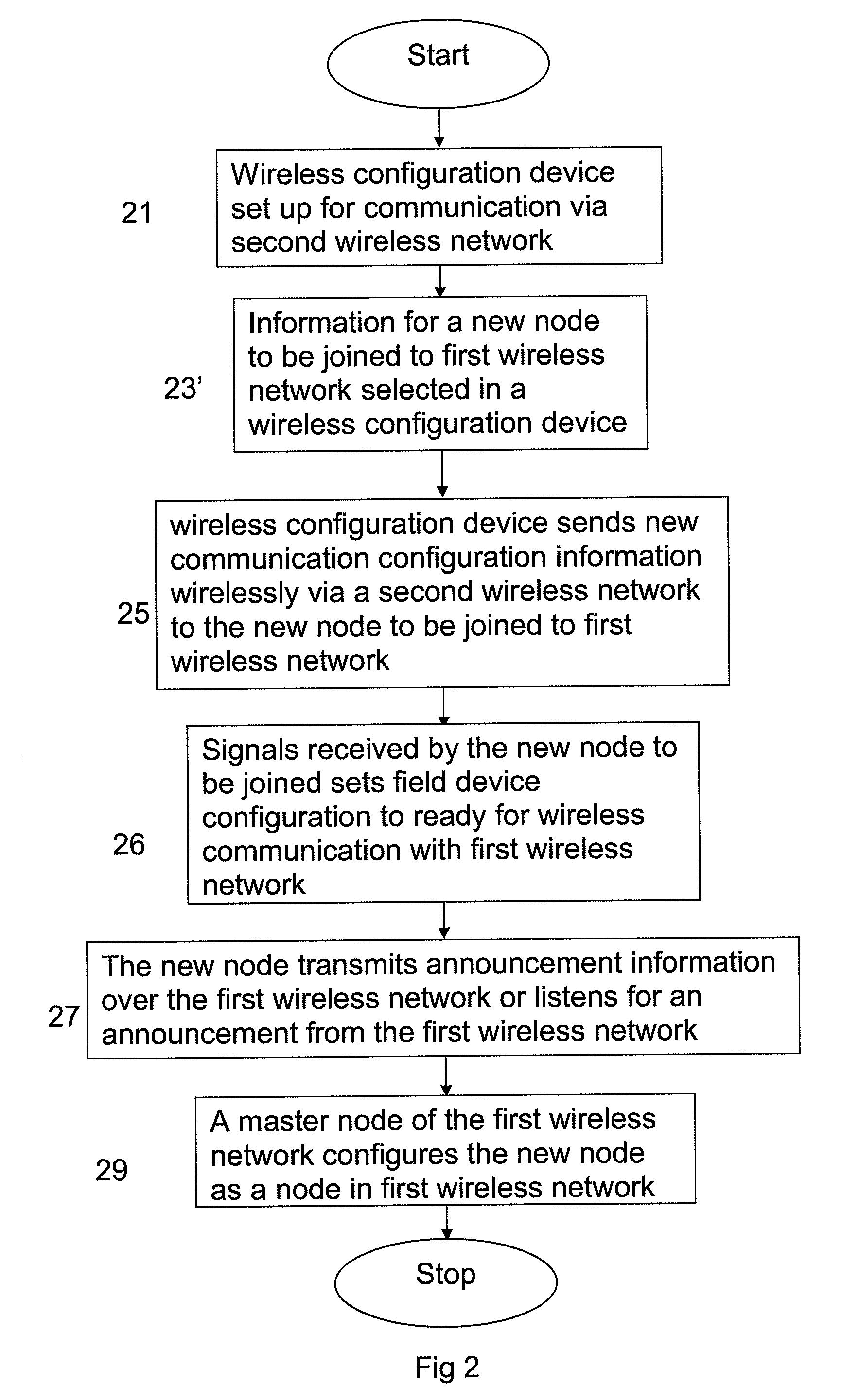
A method for joining a wireless node of a field device such as a sensor or actuator to a wireless network connected to an industrial monitoring or control system. A handheld wireless device is utilized including hardware and software for communicating with the wireless node of a field device. A new communication configuration necessary for the new node to use in order to join the wireless network is sent from the handheld device to a new node. A wireless handheld device and an industrial monitoring or control system and a computer program.

Description

CROSS-REFERENCE TO RELATED APPLICATIONS[0001]This application claims priority to European patent application 08151919.1 filed 26 Feb. 2008.TECHNICAL FIELD[0002]The invention concerns a method and a device for communicating with a field device or sensor connected to an industrial monitoring or control system. In particular the device is a wireless configuration device arranged for use with configuring a wireless node in a distributed control system, or industrial monitoring or control system arranged with a wireless data network.TECHNICAL BACKGROUND[0003]A sensor, actuator and / or measuring instrument intended to be connected to a process control system in an oil production facility, or an industrial monitoring or control system or a distributed control system (DCS) requires configuration settings in order for it to correctly perform the connection. These configuration settings are downloaded to the sensor, actuator or any other type of field device at the time it is being deployed in...

Claims


Application Information

Patent Timeline
IPC IPC(8): G08B1/08H04W84/02
CPCH04L41/0809H04L41/0879H04W88/06H04W8/005H04W48/08H04L2012/4026H04L63/18H04L67/12H04W12/50
Inventor BALGARD, LENNARTLENNVALL, TOMASSVENSSON, STEFAN
Owner ABB (SCHWEIZ) AG
Learn More