System aspects for a probe system that utilizes structured-light

a probe system and structured light technology, applied in the field of endoscopes, can solve the problems of numerous system-level challenges of endoscopes and borescopes

Active Publication Date: 2009-09-10
BAKER HUGHES OILFIELD OPERATIONS LLC
View PDF19 Cites 170 Cited by
  • Summary
  • Abstract
  • Description
  • Claims
  • Application Information

AI Technical Summary

Benefits of technology

[0006]Phase-shift technology is well suited to addressing these measurement needs, but its implementation in a borescope or endoscope presents numerous system-level challenges. It is desirable to address these challenges in a manner that yields a reliable and easy-to-use system.

Problems solved by technology

Phase-shift technology is well suited to addressing these measurement needs, but its implementation in a borescope or endoscope presents numerous system-level challenges.

Method used


Image

  • System aspects for a probe system that utilizes structured-light
  • System aspects for a probe system that utilizes structured-light
  • System aspects for a probe system that utilizes structured-light

Examples


Embodiment Construction

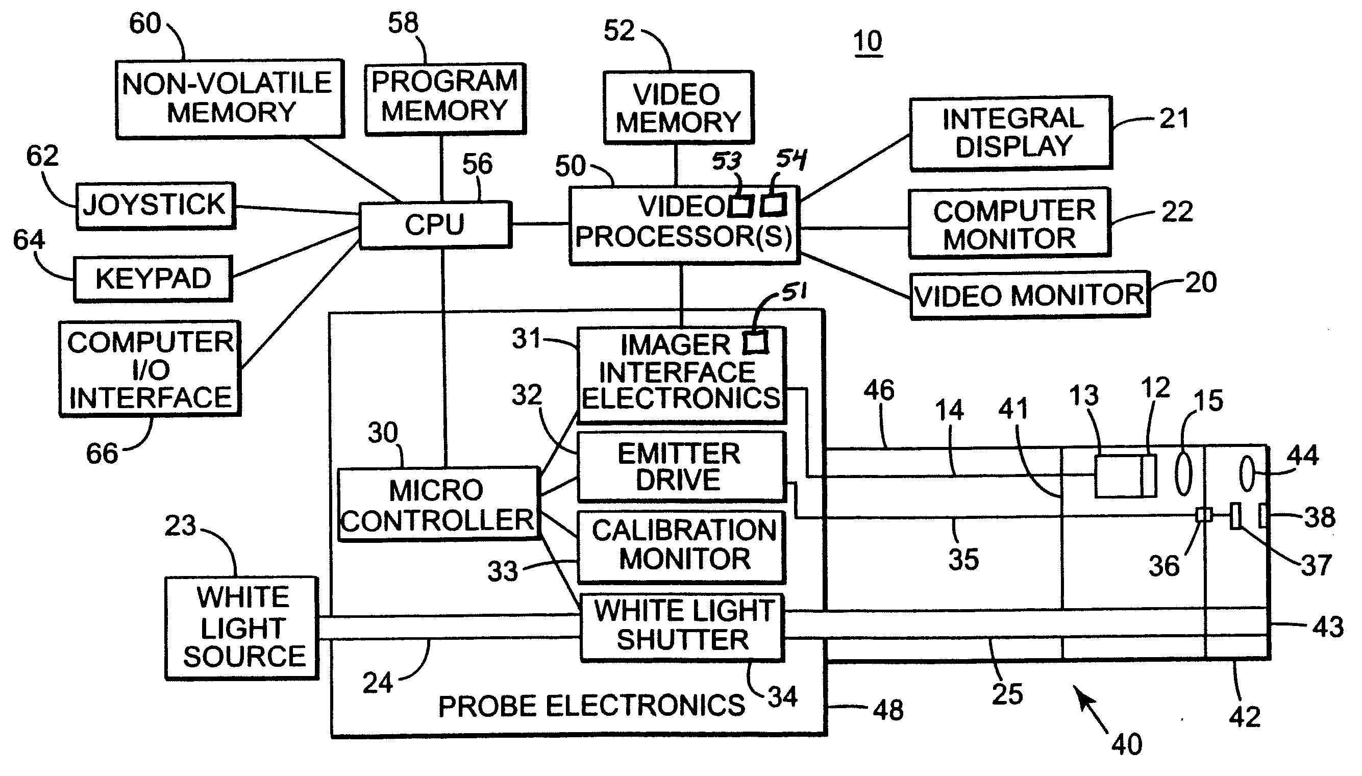
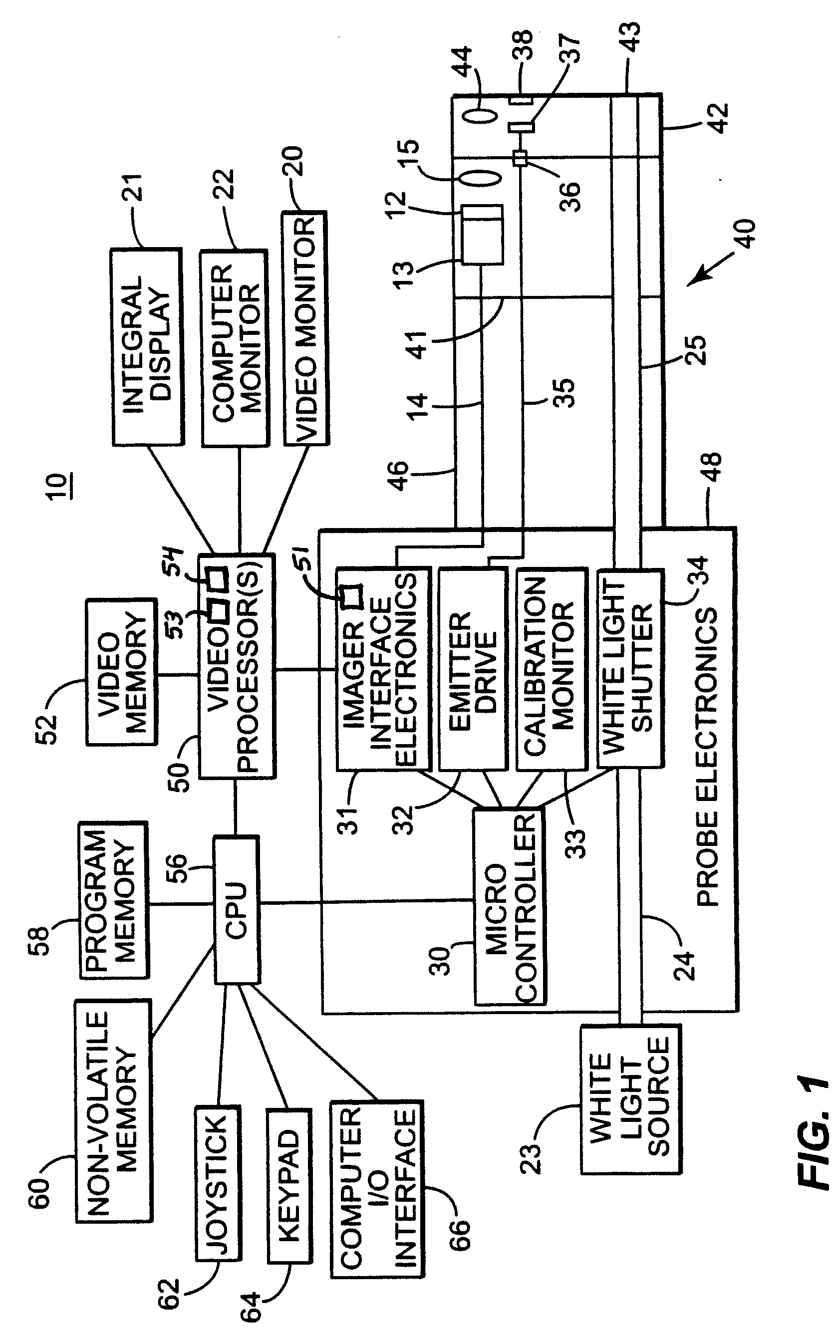
[0016]Illustrated in FIG. 1, a borescope / endoscope system or probe system 10 according to an embodiment of the invention is shown. An insertion tube 40 comprises elongated portion 46 and detachable distal tip 42. Elongated portion 46 comprises a main long, flexible portion, a bending neck, and a camera head. Delineation line 41 shows where the camera head starts on elongated portion 46. The camera head of elongated portion 46 typically includes at least imager 12, electronics 13, and probe optics 15. Detachable distal tip 42 typically attaches to the camera head of elongated portion 46, mentioned above. Detachable distal tip 42 contains viewing optics 44 which are used in combination with probe optics 15 to guide and focus light received from the viewed surface or object (not shown) onto imager 12.

[0017]The elements shown in tip 42 could alternatively be located on elongated portion 46. These elements include viewing optics 44, at least one emitter module 37, at least one intensity-...


PUM


Abstract

A probe system includes an imager and an inspection light source. The probe system is configured to operate in an inspection mode and a measurement mode. During inspection mode, the inspection light source is enabled. During measurement mode, the inspection light source is disabled, and a structured-light pattern is projected. The probe system is further configured to capture at least one measurement mode image. In the at least one measurement mode image, the structured-light pattern is projected onto an object. The probe system is configured to utilize pixel values from the at least one measurement mode image to determine at least one geometric dimension of the object. A probe system configured to detect relative movement between a probe and the object between captures of two or more of a plurality of images is also provided.

Description

CROSS-REFERENCE TO RELATED APPLICATIONS[0001]This application is a Continuation-in-Part of and claims priority from U.S. Ser. No. 12 / 042,821 filed Mar. 5, 2008 entitled Fringe Projection System and Method for a Probe Suitable for Phase-Shift Analysis, which is incorporated herein by reference.BACKGROUND OF THE INVENTION[0002]1. Field of the Invention[0003]The subject matter described herein relates generally to borescopes and endoscopes, and more particularly, to a borescope / endoscope which provides 3D surface mapping and dimensional measurement.[0004]2. Related Art[0005]Borescopes and endoscopes are typically used for inspection inside a remote cavity. Most borescopes / endoscopes, referred to herein as a probe, employ an external light source coupled to fiber optic bundles in the probe to provide illumination of a remote object or surface at the distal end. When the object is illuminated, an internal image is formed by a lens system on an image sensor, and the image is relayed to a ...

Claims


Application Information

Patent Timeline
Patent Type & Authority Applications(United States)
IPC IPC(8): G01B11/02
CPCG01N21/954G01B11/25G06T7/0057G01N2021/9544G06T7/521
Inventor BENDALL, CLARK ALEXANDERHARDING, KEVIN GEORGEKARPEN, THOMASSONG, GUIJUTAO, LI
Owner BAKER HUGHES OILFIELD OPERATIONS LLC
Why Eureka
Try Eureka