Method and apparatus for a leakage energy recovery circuit

a leakage energy recovery and circuit technology, applied in the direction of electric variable regulation, process and machine control, instruments, etc., can solve the problems of voltage surge which could damage the switch, leakage inductance in the transformer, and decrease the overall efficiency of the inverter

Inactive Publication Date: 2009-09-10
ENPHASE ENERGY
View PDF19 Cites 55 Cited by
  • Summary
  • Abstract
  • Description
  • Claims
  • Application Information

AI Technical Summary

Problems solved by technology

The magnetic flux also traverses paths outside the windings, resulting in leakage inductance in the transformer.
The energy stored in the leakage inductance cannot be transferred to the secondary winding, and a quick change in the primary current, such as when the control switch turns off, will induce a voltage surge which could damage the switch.
Such designs waste the energy of the leakage energy, which decreases the overall efficiency of the inverter.

Method used


Image

  • Method and apparatus for a leakage energy recovery circuit
  • Method and apparatus for a leakage energy recovery circuit
  • Method and apparatus for a leakage energy recovery circuit

Examples


Embodiment Construction

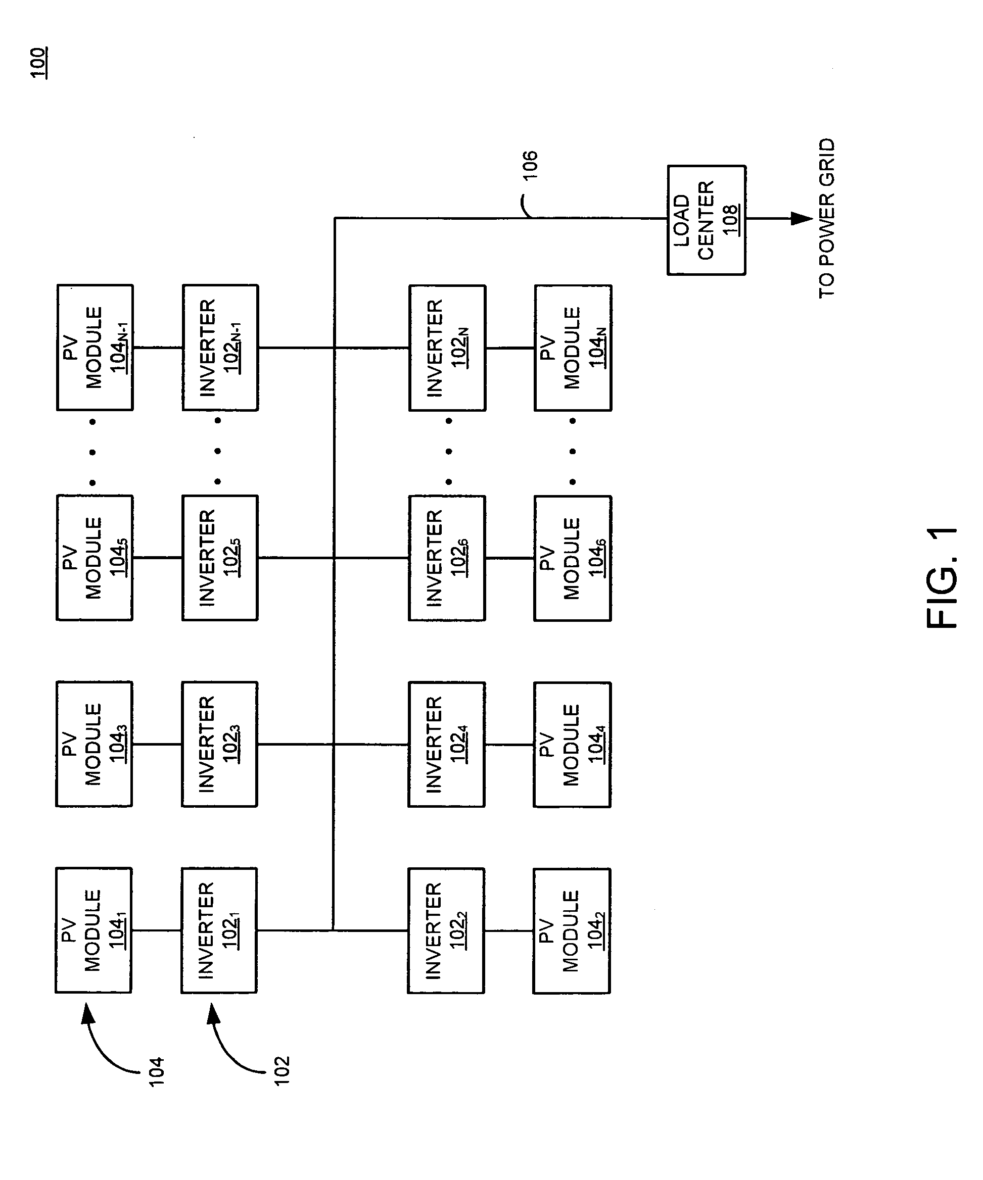
[0015]FIG. 1 is a block diagram of a system 100 for distributed generation (DG) in accordance with one or more embodiments of the present invention. This diagram only portrays one variation of the myriad of possible system configurations. The present invention can function in a variety of distributed power generation environments and systems.

[0016]The system 100 comprises a plurality of inverters 1021, 1022 . . . 102n, collectively referred to as inverters 102, a plurality of PV modules 1041, 1042 . . . 104n, collectively referred to as PV modules 104, an AC bus 106, and a load center 108. Each inverter1021, 1022 . . . 102n is coupled to a PV module 1041, 1042 . . . 104n, respectively. Alternatively, multiple PV modules 104 may be coupled to a single inverter 102 (i.e., a centralized inverter). In other embodiments, the inverters 102 may receive input from DC sources other than PV modules.

[0017]The inverters 102 are coupled to the AC bus 106, which in turn is coupled to the load cen...


PUM


Abstract

A method and apparatus for recovering leakage energy during DC power to AC power conversion. The apparatus comprises a leakage energy recovery circuit for storing leakage energy from a transformer and selectively coupling stored leakage energy to an input of the transformer.

Description

CROSS-REFERENCE TO RELATED APPLICATIONS[0001]This application claims benefit of U.S. provisional patent application Ser. No. 61 / 068,296, filed Mar. 6, 2008, which is herein incorporated in its entirety by reference.BACKGROUND OF THE INVENTION[0002]1. Field of the Invention[0003]Embodiments of the present invention generally relate to a power inverter and, more particularly, to utilizing a leakage energy recovery circuit to enhance the efficiency of a power inverter.[0004]2. Description of the Related Art[0005]Inverters denote a class of power conversion circuits used to produce AC power from DC power. Such inverters find widespread use in alternative energy systems where solar panels, wind turbines, hydroelectric generators, and the like produce DC power that requires conversion to AC power to facilitate coupling the generated power to the AC commercial power grid. In such systems, the power conversion process must be performed in an efficient manner.[0006]Conventionally, inverter c...

Claims


Application Information

Patent Timeline
Patent Type & Authority Applications(United States)
IPC IPC(8): H02M7/00
CPCH02M3/335H02M7/4807H02M2001/342Y02B70/1491H02M2001/0048H02J3/386Y02E10/563Y02E10/763H02J3/383H02J2300/28H02J2300/24H02J3/381Y02B70/10Y02E10/56Y02E10/76H02J3/40H02M1/0048H02M1/342
Inventor FORNAGE, MARTIN
Owner ENPHASE ENERGY
Why Eureka
Try Eureka