Coding device and method, decoding device and method, recording medium, and program

a decoding device and coding method technology, applied in the field of en decoding apparatus and encoding methods, recording media, and programs, can solve the problems of insufficient information provided in document 3 for field/frame encoding, and cannot support a higher compression ratio encoding schem

Active Publication Date: 2009-09-10
SONY CORP
View PDF5 Cites 49 Cited by
  • Summary
  • Abstract
  • Description
  • Claims
  • Application Information

AI Technical Summary

Problems solved by technology

Since MPEG2 is mainly intended for a high quality encoding technique suitable for broadcasting, it does not support an encoding scheme for a higher compression ratio.
Thus, the information provided in Document 3 is not sufficient to carry out field / frame encoding at the macroblock level using the CABAC scheme.

Method used


Image

  • Coding device and method, decoding device and method, recording medium, and program
  • Coding device and method, decoding device and method, recording medium, and program
  • Coding device and method, decoding device and method, recording medium, and program

Examples


Embodiment Construction

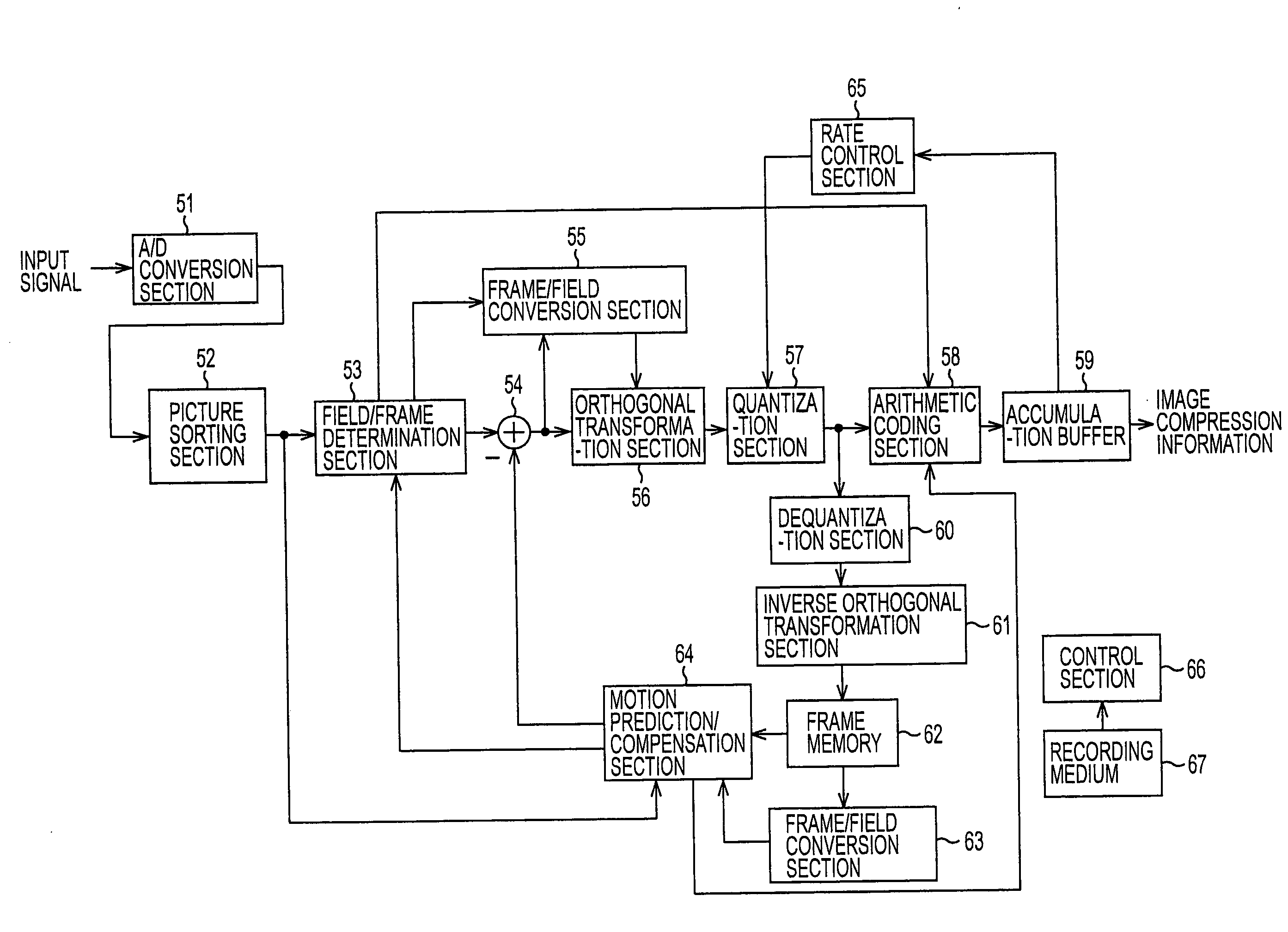
[0183]An image information encoding apparatus to which the present invention is applied will now be described with reference to FIG. 26. The relevant image information encoding apparatus enables encoding to be performed using the CABAC scheme even when input image information has an interlaced scan format.

[0184]In the relevant image information encoding apparatus, an A / D conversion section 51 converts an input image signal as an analog signal to a digital signal and outputs it to a picture sorting buffer 52. The picture sorting buffer 52 rearranges the input image information from the A / D conversion section 51 according to the GOP structure of the image compression information which is output from the relevant image information encoding apparatus and outputs it to an adder 54.

[0185]A field / frame determination section 53 determines which of frame-based encoding and field-based encoding provides a higher encoding efficiency to encode the macroblock of the image to be processed, genera...


PUM


Abstract

An encoding apparatus and an encoding method, a decoding apparatus and a decoding method, a recording medium, and a program suitable for encoding image signals with a higher compression ratio for transmission or accumulation. In an arithmetic coding section, from among the syntax elements of input image compression information, the frame / field flag is first encoded by a frame / field flag context model. When the macroblock to be processed is subjected to frame-based encoding, a frame-based context model, specified in the current H.26L standard, is applied. On the other hand, when the macroblock to be processed is subjected to field-based encoding, a field-based context model is applied for the syntax elements described below. The present invention is applied to an encoder for encoding image information and a decoder for decoding image information.

Description

CROSS-REFERENCE TO RELATED APPLICATION[0001]This application is a continuation application of U.S. application Ser. No. 10 / 509,682, filed on Oct. 12, 2004. U.S. Ser. No. 10 / 509,682 is a National Stage application of PCT / JP03 / 05081 filed on Apr. 22, 2003, and claims priority to Japanese Patent Application No. JP2002-125295, filed on Apr. 26, 2002. The entire contents of the above-identified applications are incorporated herein by reference.TECHNICAL FIELD[0002]The present invention relates to an encoding apparatus and an encoding method, a decoding apparatus and a decoding method, a recording medium, and a program. The present invention relates to, for example, an encoding apparatus and an encoding method, a decoding apparatus and a decoding method, a recording medium, and a program suitable for encoding image signals with a higher compression ratio for transmission or accumulation.BACKGROUND ART[0003]Nowadays, apparatuses in compliance with, for example, MPEG (Moving Picture Expert ...

Claims


Application Information

Patent Timeline
Patent Type & Authority Applications(United States)
IPC IPC(8): H04N7/26H04N19/13G06T9/00H03M7/32H03M7/40H03M13/07H04N19/00H04N19/105H04N19/11H04N19/136H04N19/159H04N19/46H04N19/463H04N19/503H04N19/51H04N19/517H04N19/523H04N19/577H04N19/60H04N19/61H04N19/625H04N19/70H04N19/91
CPCH03M7/4006H04N19/176H04N19/00684H04N19/13H04N19/16H04N19/513H04N19/52H04N19/537
Inventor SATO, KAZUSHISUZUKI, TERUHIKOSUNOHARA, OSAMUYAGASAKI, YOICHI
Owner SONY CORP
Why Eureka
Try Eureka