Method for Catalytic Recombination of Hydrogen, Which is Carried in a Gas Flow, With Oxygen, and a Recombination System for Carrying out the Method

a technology of catalytic recombination and hydrogen, which is applied in the field of catalytic recombination of hydrogen, can solve the problems of recombination unit operating outside its stable operating parameters, affecting the and affecting the efficiency of recombination devices, etc., and achieves the effect of high operational reliability of recombination devices

Inactive Publication Date: 2009-09-10
AREVA GMBH
View PDF6 Cites 21 Cited by
  • Summary
  • Abstract
  • Description
  • Claims
  • Application Information

AI Technical Summary

Benefits of technology

[0010]It is accordingly an object of the invention to provide a method for catalytic recombination of hydrogen, which is carried in a gas flow, with oxygen, and a recombination system for carrying out the method which overcomes the above-mentioned disadvantages of the prior art devices of this general type. The invention is therefore based on the object of specifying a method of the abovementioned type for catalytic recombination of hydrogen, which is carried in a gas flow, with oxygen, by which, even in the case of the operating conditions or ways of operation, which vary in this case, a particularly high operational reliability of the recombination device is ensured, particularly with regard to hydrogen feed which is provided as required in the primary circuit of the installation.

Problems solved by technology

However, particularly with regard to the varying operating conditions and methods, this case corresponds to an extreme exceptional situation, as a result of which the added steam or dilution steam is fed to a considerably excessive extent to the system throughout the vast majority of the operating range of an installation such as this.
Such overfeeding of this system with added steam, which goes well beyond the actual requirement, should, however, be avoided since, on the one hand, undesirably high steam consumption must be accepted as a result of such overfeeding and since, on the other hand, with such overfeeding, the proportion of hydrogen in the gas flow entering into the reaction zone in most operating situations of the installation is so low that the recombination unit operates outside its stable operating parameters, and therefore only unreliably.

Method used


Image

  • Method for Catalytic Recombination of Hydrogen, Which is Carried in a Gas Flow, With Oxygen, and a Recombination System for Carrying out the Method
  • Method for Catalytic Recombination of Hydrogen, Which is Carried in a Gas Flow, With Oxygen, and a Recombination System for Carrying out the Method
  • Method for Catalytic Recombination of Hydrogen, Which is Carried in a Gas Flow, With Oxygen, and a Recombination System for Carrying out the Method

Examples


Embodiment Construction

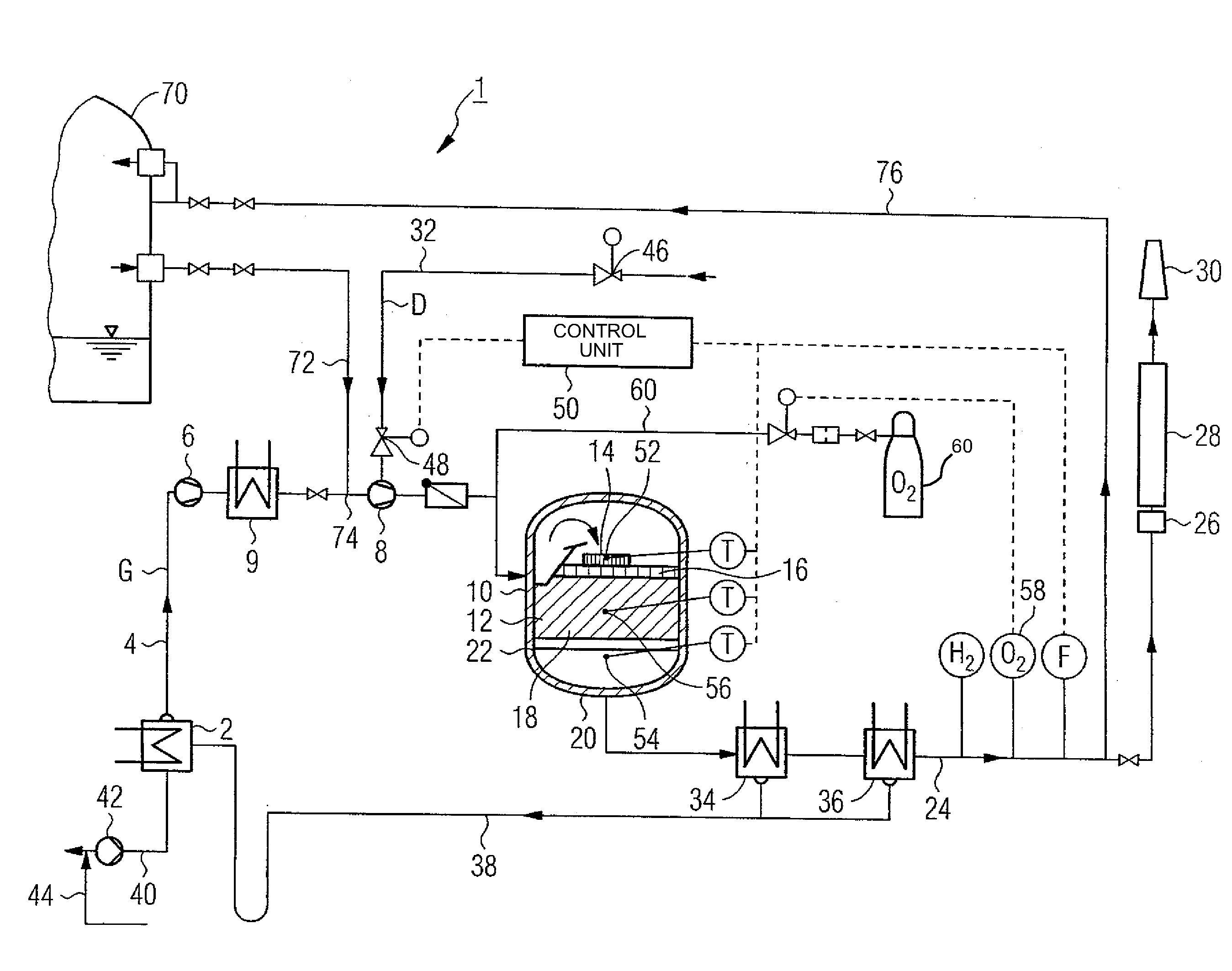
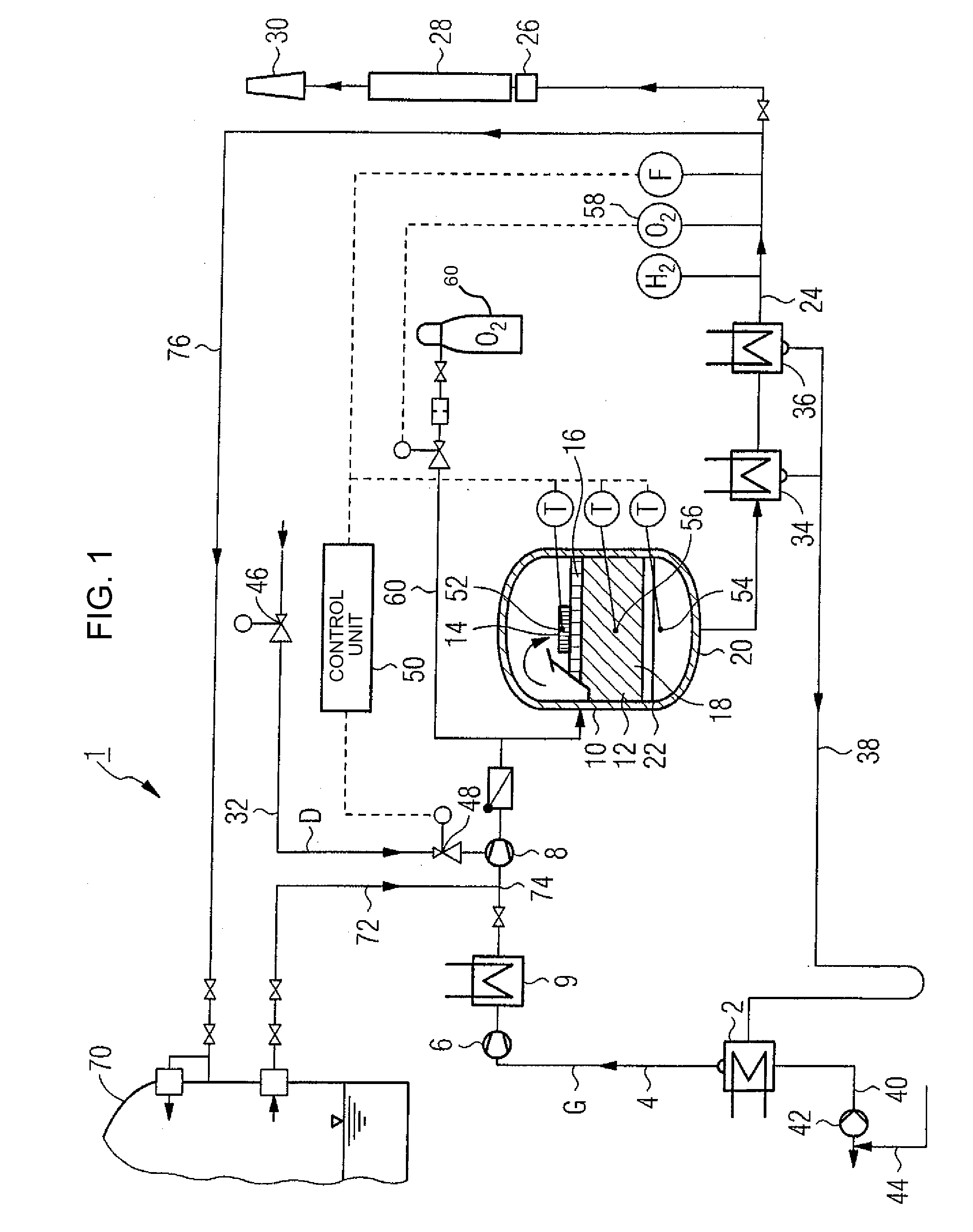
[0028]Identical parts are provided with the same reference symbols in the two figures. Referring now to the figures of the drawing in detail and first, particularly, to FIG. 1 thereof, there is shown a recombination system 1 that is configured for catalytic recombination of a combustible gas, that is to say hydrogen in the exemplary embodiment. In the exemplary embodiment, the recombination system 1 is in this case intended for gas processing or treatment for a turbine condenser 2 of a nuclear power station. For this purpose, an inlet line 4 of the recombination system 1 is connected on an input side, in the form of a purging system, to the turbine condenser 2 of the nuclear power station. On an output side, the inlet line 4 into which a primary compressor 6 and a secondary compressor 8 are connected in order to feed the gas flow G which requires treatment, is connected to a recombination unit 10.

[0029]The recombination unit 10 is in this case configured for the actual catalytic rec...


PUM


Abstract

A method and a system for catalytic recombination of hydrogen, which is carried in a gas flow, with oxygen, has the gas flow passed through a reaction zone with a number of catalytic converter elements, with steam being added to the gas flow before it enters the reaction zone. The method and system ensure a particularly high operational reliability of the recombination device, even in varying operating conditions or with varying operating methods, in particular with regard to a hydrogen feed, which is provided as required, in the steam/feed water circuit of the installation. For this purpose, the feed rate of the steam to be added is adjusted in dependence on a measured value which is characteristic of a current actual temperature in the reaction zone.

Description

CROSS-REFERENCE TO RELATED APPLICATION[0001]This application claims the priority, under 35 U.S.C. § 119, of German application DE 10 2008 013 213.6-54, filed Mar. 7, 2008; the prior application is herewith incorporated by reference in its entirety.BACKGROUND OF THE INVENTIONField of the Invention[0002]The invention relates to a method for catalytic recombination of hydrogen, which is carried in a gas flow, with oxygen, in which the gas flow is passed through a reaction zone with a number of catalytic converter elements, with steam being added to the gas flow before it enters the reaction zone. It also relates to a recombination system for catalytic recombination of hydrogen, which is carried in a gas flow, with oxygen, in which an inlet line, which is provided in order to supply the gas flow into a reaction zone which is formed by a number of catalytic converter elements, is connected to a steam supply line, in order to add steam as required.[0003]In many technical installation, the...

Claims


Application Information

Patent Timeline
Patent Type & Authority Applications(United States)
IPC IPC(8): G21C9/06
CPCG21C9/06G21C19/317G21Y2002/201G21Y2002/206Y02E30/40G21Y2002/50G21Y2004/30G21Y2004/403G21Y2002/207Y02E30/30
Inventor ECKARDT, BERNDFEUERBACH, ROBERT
Owner AREVA GMBH
Why Eureka
Try Eureka