Dental furnace

Active Publication Date: 2009-09-10
IVOCLAR VIVADENT AG
View PDF15 Cites 20 Cited by
  • Summary
  • Abstract
  • Description
  • Claims
  • Application Information

AI Technical Summary

Benefits of technology

[0031]By obviating kiln furniture, it is possible to further reduce the heat capacity or thermal mass in relation to kilns having kiln furniture. It is also particularly expedient according to the invention if, instead of passive cooling, active cooling is also effected precisely in the interspace between the thermal insulation and the heating elem

Problems solved by technology

However, this is complicated and greatly dependent on the operator's care.
Moreover, the mass of the introduced dental material cannot usually be ascertained exactly.
Although this method is good in principle, it is diametrically opposite to the desires in the dental laboratory to save costs by means of a short production cycle.
Furthermore, U.S. Pat. No. 6,025,065 has,

Method used


Image

  • Dental furnace
  • Dental furnace
  • Dental furnace

Examples


Embodiment Construction

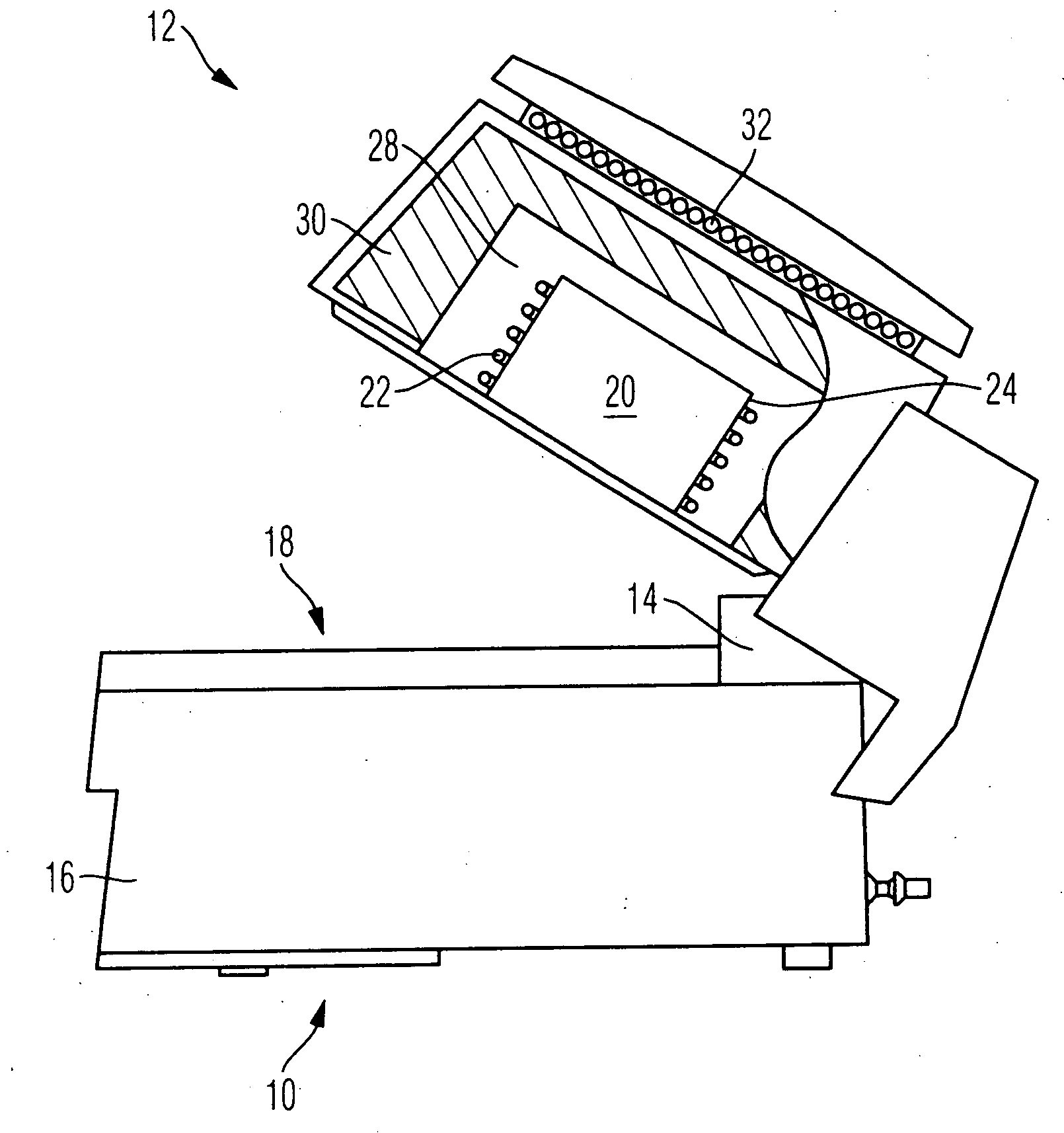
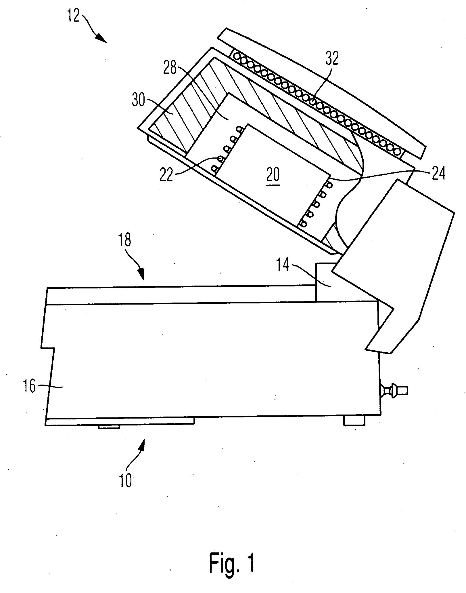
[0050]The dental furnace 10 illustrated in FIG. 1 has a furnace hood 12, which is mounted on a furnace lower part 16 by means of a pivoting articulated joint 14. The lower part 16 has on its top side a bearing surface 18, which is intended for receiving the dental material to be fired. A firing chamber 20 is provided in the furnace hood 12, and it extends in the manner of a rather flat cylinder and, with the furnace hood 12 closed, is closed off at the bottom by the bearing surface 18, such that the bearing surface 18 forms the bottom of the firing chamber 20.

[0051]The firing chamber 20 is surrounded annularly or spirally by heating elements 22.

[0052]According to the invention, particularly powerful heating elements are provided, which are designed such that they are fundamentally able to heat up the furnace from room temperature to 1600° C. within approximately a quarter of an hour. The dental furnace accordingly has a max. temperature gradient of 120° K / min.

[0053]The heat capacity...


PUM

PropertyMeasurementUnit
Temperatureaaaaaaaaaa

Abstract

The invention relates to a dental furnace wherein a firing chamber is heated up in a first heating-up period at a first heating-up rate of more than 50° K/min, in particular more than 100° K/min, which heats the furnace to at least 1000° C., in particular to 1100-1250° C. The first heating-up period is followed by an intermediate heating period, which is at least five minutes long, in particular at least ten minutes long, the gradient or heating-up rate of which is adapted to the material to be sintered in the dental furnace (10), and wherein this is followed by an end heating-up period (44) during which heating up is effected at a heating-up rate of more than 30° K/min, in particular approximately 50° K/min, and wherein during this the furnace temperature is held for at least five minutes, in particular for at least 25 minutes, above the temperature toward the end of the first heating-up period, and wherein forced cooling of the furnace (10) is performed after this.

Description

CROSS-REFERENCE TO RELATED APPLICATIONS[0001]This application claims foreign priority benefits under 35 U.S.C. §119(a)-(d) from German patent application ser. no. P 10 2008 012 578.4 filed Mar. 5, 2008.TECHNICAL FIELD[0002]The invention relates to a dental furnace which is heated up in stages and also cooled down to a method for heating up and cooling down, and more particularly to such a furnace used for sintering dental materials.BACKGROUND OF THE INVENTION[0003]A dental furnace of this type and a method of this type have long been known. Precisely for sintering adapted dental materials it is important to cause the heating up, the actual firing, and indeed the cooling down as well, to proceed according to a predetermined and reproducible scheme in order on the one hand to ensure the required material compaction, but on the other hand also to ensure that the shrinkage takes place uniformly to the entire extent.[0004]For this purpose, the temperature in the interior of the dental fu...

Claims


Application Information

Patent Timeline
IPC IPC(8): F27D9/00F27D1/00
CPCC04B2235/6562C04B35/111F27B17/025C04B35/64A61C13/20C04B35/486C04B2235/656F27D9/00F27D11/04F27D19/00F27D2009/007F27D2019/0037F27D2019/0056
Inventor ROHNER, GOTTFRIEDPOKORNY, WALTERGRUNENFELDER, ROBERTROTHBRUST, FRANK
Owner IVOCLAR VIVADENT AG
Why Eureka
Try Eureka