Method for manufacturing ignition plug

Inactive Publication Date: 2009-09-10
NGK SPARK PLUG CO LTD
View PDF10 Cites 14 Cited by
  • Summary
  • Abstract
  • Description
  • Claims
  • Application Information

AI Technical Summary

Benefits of technology

[0006]Accordingly, it is an aspect of the invention to provide a manufacturing method of an ignition plug which can eliminate a shift in position between a center axis of a through hole provided in the center of a ground electrode and a center axis of a cavity provided in an insulator.
[0009]According to the manufacturing method of the aspect of the invention described above, the center of the through hole of the ground electrode and the center of the cavity of the insulator can be positioned before the ground electrode and the metal shell are welded together. Because of this, a shift in position between a center axis of the through hole and a center axis of the cavity can be eliminated.

Problems solved by technology

In the manufacturing method described above, however, in the step (3), there was a case where when the insulator was made to be held within the metal shell, a shift in position, or “position error,” occurred between the center axis of the through hole in the center of the ground electrode and the center axis of a cavity provided on the insulator.
As this occurred, there was concern that spark discharge was performed locally, resulting in a phenomenon in which the ground electrode became worn locally.
In addition, when the center axis of the through hole in the center of the ground electrode shifted from the center axis of the cavity provided on the insulator, there was concern that part of the cavity which functioned as a discharge space was closed by the ground electrode, and as this occurred, a quenching action was caused, resulting in a fear that the igniting performance was reduced.

Method used


Image

  • Method for manufacturing ignition plug
  • Method for manufacturing ignition plug
  • Method for manufacturing ignition plug

Examples


first exemplary embodiment

B. First Exemplary Embodiment

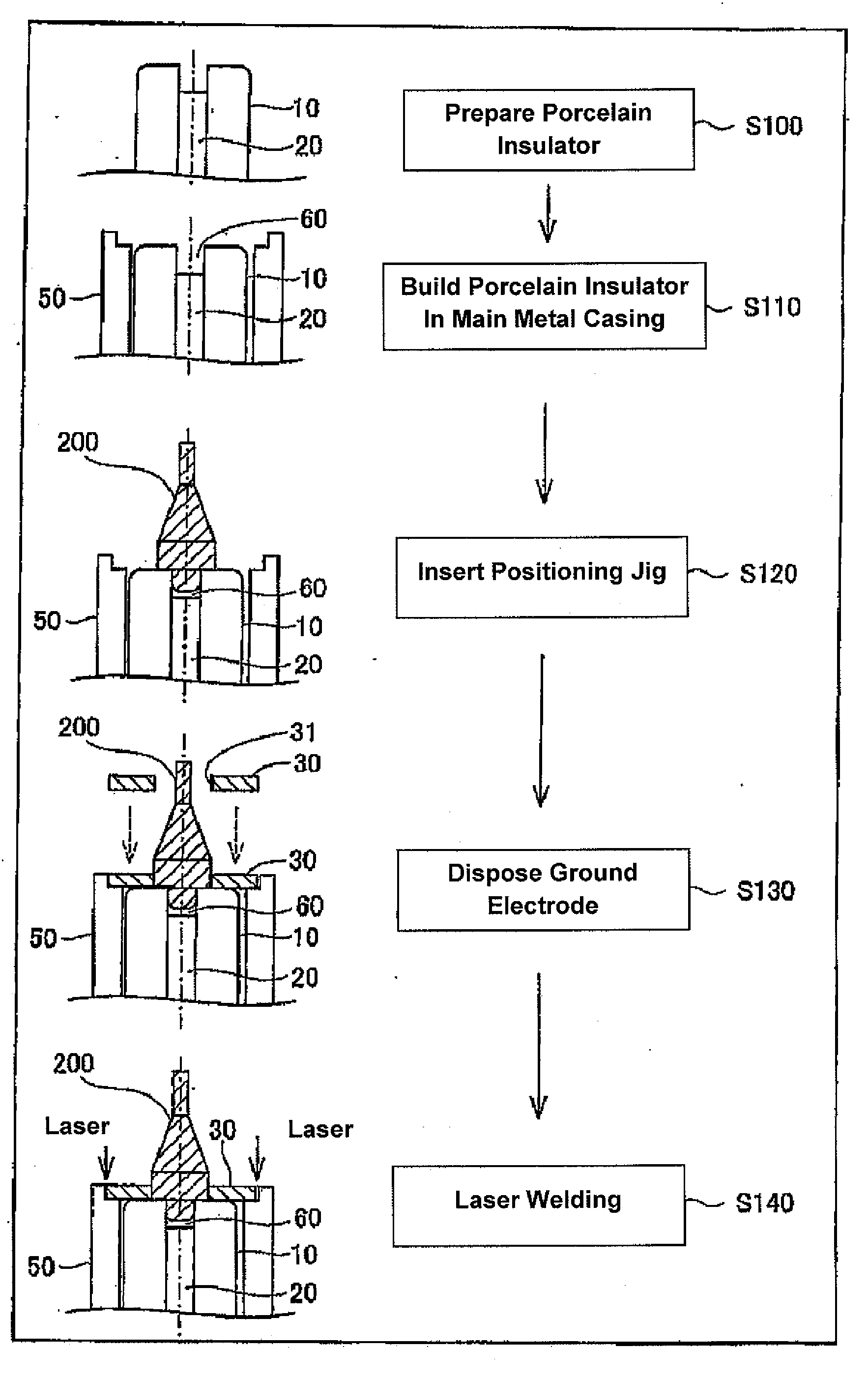
[0043]FIG. 3 is a diagram showing an ignition plug manufacturing method according to a first exemplary embodiment of the invention. As shown in FIG. 3, in this embodiment, firstly, a porcelain insulator 10, in which a center electrode 20 is assembled in advance, is prepared in a separate manufacturing step (step S100: a preparation step). Then, the porcelain insulator 10 is inserted into a metal shell 50, and by a crimped portion 53 of the metal shell 50 being crimped, the porcelain insulator 10 is built in the metal shell 50 (step S110: a build-in step). In addition, a predetermined positioning jig 200 is inserted into a cavity 60 (a cavity 60) provided at a leading end of the porcelain insulator 10 (step S120: a positioning step).

[0044]FIG. 4 is a side view of the positioning jig 200, and FIG. 5 is a bottom view of the positioning jig 200 as viewed from a rear end side of an axis O thereof. As shown in FIG. 4, the positioning jig 200 has a head portion...

second exemplary embodiment

C. Second Exemplary Embodiment

[0048]FIG. 6 is a diagram showing an ignition plug manufacturing method according to a second exemplary embodiment of the invention. As shown in FIG. 6, in this embodiment, steps S100 to S130 which were described in the first exemplary embodiment above, are performed. In this respect, a porcelain insulator 10, in which a center electrode 20 is assembled, is prepared (step S200: a preparation step). The porcelain insulator 10 so prepared is assembled in a metal shell 50 (step S210: a build-in step). A positioning jig 200 is inserted in a cavity 60 at a leading end of the porcelain insulator 10 (step S220: a positioning step) Then, a ground electrode 30 having a through hole 31 is moved down onto the positioning jig 200 from a leg portion 203 side thereof, so that the ground electrode 30 is placed in a fitting stepped portion 58 at a leading end of the metal shell 50 (step S230: a disposing step +a positioning step).

[0049]Following this, according to this...

third exemplary embodiment

D. Third Exemplary Embodiment

[0053]FIG. 9 is a diagram showing an ignition plug manufacturing method according to a third exemplary embodiment of the invention. As shown in FIG. 9, in this embodiment, firstly, similar to steps S100, S110 which were described in the first exemplary embodiment above, a porcelain insulator 10 in which a center electrode 20 is assembled is prepared (step S300: a preparation step) and the porcelain insulator 10 so prepared is then assembled in a metal shell 50 (step S310: a build-in step).

[0054]Following this, in this embodiment, a ground electrode 30 is placed in a fitting stepped portion 58 in a leading end of the metal shell 50 (step S320: a disposing step). Then, an integral jig 400, which doubles as both the positioning jig 200 illustrated in the first exemplary embodiment and the pressing jig 300 illustrated in the second exemplary embodiment, is fitted in a cavity 60 at a leading end of the porcelain insulator 10 and a through hole 31 of the groun...


PUM


Abstract

A method for manufacturing an ignition plug is provided. The method includes: preparing an insulator having a cavity provided at a leading end portion thereof by disposing a leading end of a center electrode more inwards in an axial hole than a leading end of the insulator; building the insulator in an interior of a metal shell; disposing a ground electrode at a leading end portion of the metal shell; positioning a center of a through hole of the ground electrode and a center of the cavity of the insulator; and welding the ground electrode and the metal shell together after the positioning step.

Description

FIELD OF THE INVENTION[0001]The present invention relate to a method for manufacturing ignition plug such as a plasma-jet spark plug.BACKGROUND OF THE INVENTION[0002]Conventionally, spark plugs which ignite air-fuel mixtures by spark discharge have been used for ignition plugs for internal combustion engines of automobiles. In recent years, higher power outputs and lower fuel consumptions have been demanded of such internal combustion engines. Because of this, efforts have been made to develop plasma-jet spark plugs that can ignite leaner air-fuel mixtures which burn out quickly and whose ignitable limit air-fuel ratios are higher[0003]For example, Japanese unexamined patent application publication No. JP-A-2007-287666 describes a related art plasma-jet spark plug. The related art plasma-jet spark plug has a structure in which a cavity having a small capacity is formed as a discharge space by surrounding the periphery of a spark discharge gap between a center electrode and a ground ...

Claims


Application Information

Patent Timeline
IPC IPC(8): H01T21/02
CPCH01T21/02
Inventor NAKAMURA, TORUKATO, TOMOAKIYAMADA, YUICHI
Owner NGK SPARK PLUG CO LTD
Why Eureka
Try Eureka