Electromechanical Lock and Its Operation Method

a technology applied in the field of electromechanical locks and electromechanical locks, can solve the problems of normal electromechanical locks that require external supplies, and achieve the effect of improving electromechanical and improving the method of operating an electromechanical lock

Active Publication Date: 2009-09-17
ILOQ OY
View PDF7 Cites 17 Cited by
  • Summary
  • Abstract
  • Description
  • Claims
  • Application Information

AI Technical Summary

Benefits of technology

[0005]The present invention seeks to provide an improved electromechanic

Problems solved by technology

One problem associated with the replacement is that a normal electromechanical lock requires an external supply for electric power, or a battery inside the lock, or a battery inside the key.

Method used


Image

  • Electromechanical Lock and Its Operation Method
  • Electromechanical Lock and Its Operation Method
  • Electromechanical Lock and Its Operation Method

Examples


Embodiment Construction

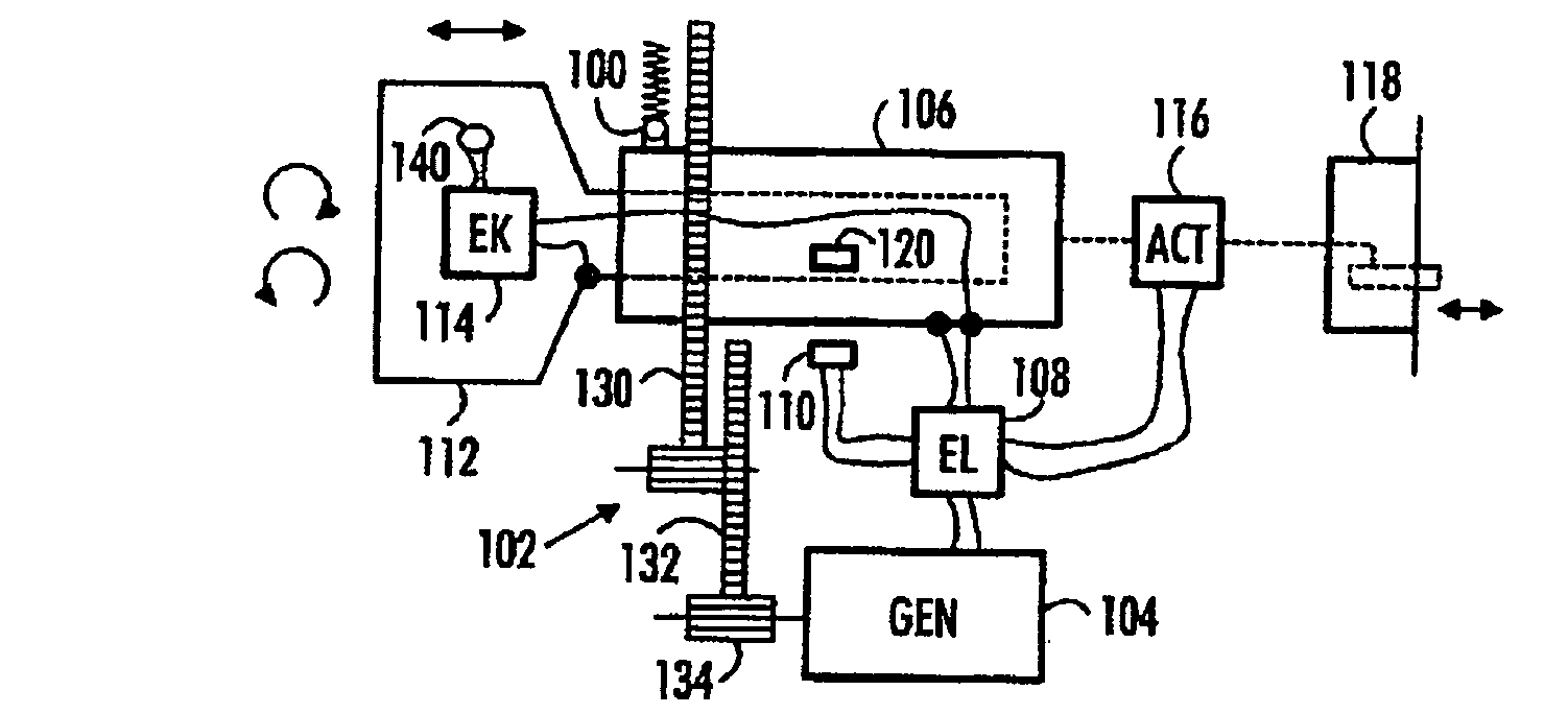
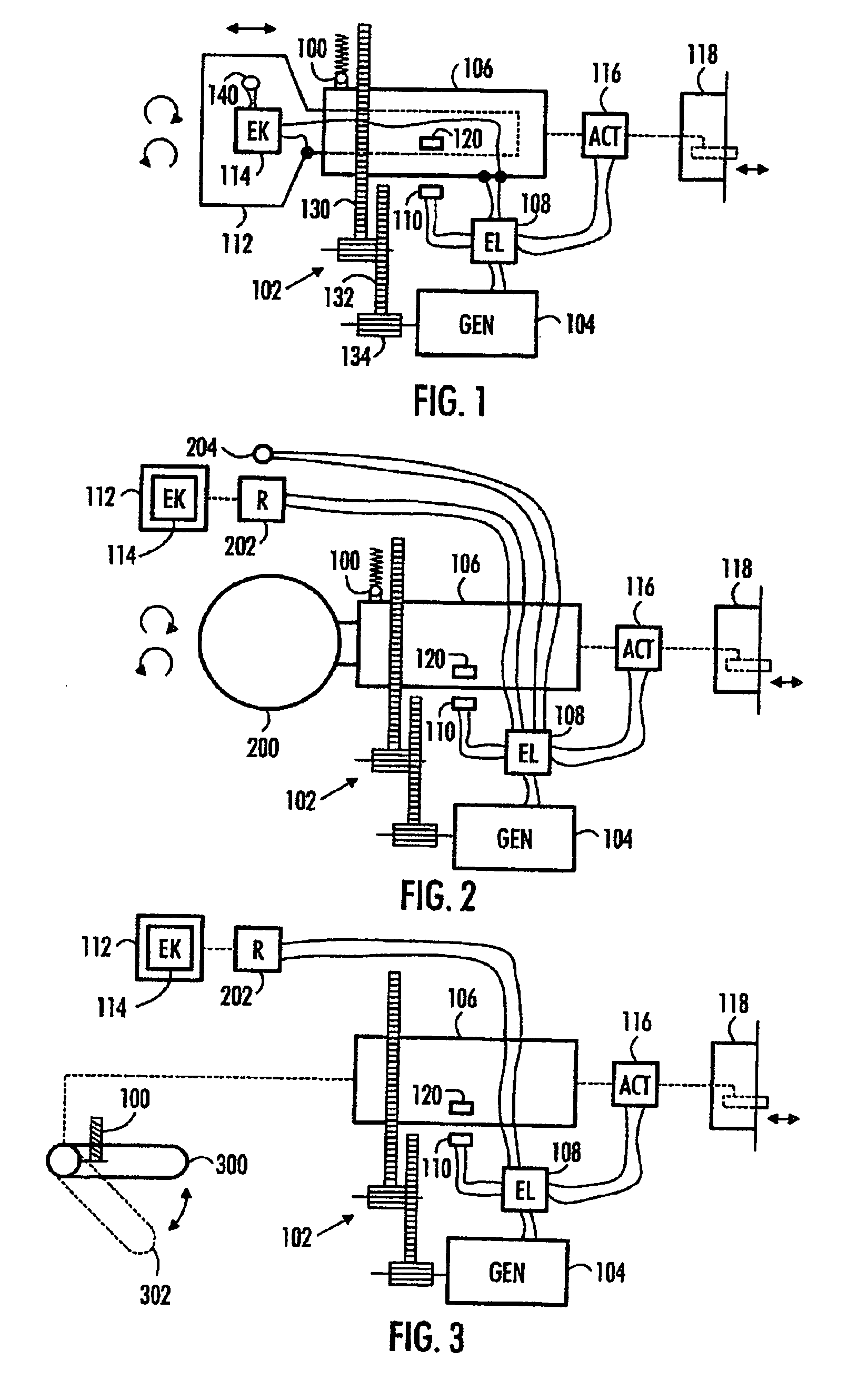
[0025]FIGS. 1, 2 and 3 illustrate various turn-powered electromechanical locks: the lock comprises a power transmission mechanism 102 to receive mechanical power produced by a user of the lock.

[0026]In FIG. 1, the power transmission mechanism 102 comprises a mechanism to receive the mechanical power while the user is turning a key 112 in the lock, in FIG. 2, a knob 200 to receive the mechanical power while the user is turning the knob 200, and in FIG. 3, a handle 300 to receive the mechanical power while the user is turning the handle 300. Other suitable turning mechanisms may be used as the power transmission mechanism 102 as well.

[0027]The lock further comprises a generator 104 to produce electric power from the mechanical power. The generator 104 may be a permanent magnet generator. The output power of the generator 104 depends on rotating speed, terminal resistance and terminal voltage of the electronic and the constants of the generator 104. The generator constants are set when...


PUM


Abstract

Electromechanical lock and its operation method. The lock includes a power transmission mechanism to receive mechanical power produced by a user of the lock; a generator to produce electric power from the mechanical power; an electronic circuit, powered by the electric power, coupleable with a key, to read data from the key, and to issue an open command provided that the data matches a predetermined criterion; an actuator, powered by the electric power, to receive the open command, and to set the lock in a mechanically openable state; and a threshold device to control the power transmission mechanism so that a mechanical tension rises until a predetermined force threshold is exceeded, whereupon the mechanical tension transforms to an action producing the mechanical power received by the power transmission mechanism.

Description

FIELD[0001]The invention relates to an electromechanical lock and a method for operating an electromechanical lock.BACKGROUND[0002]Various types of electromechanical locks are replacing the traditional mechanical locks. One problem associated with the replacement is that a normal electromechanical lock requires an external supply for electric power, or a battery inside the lock, or a battery inside the key. Wiring of the lock may become necessary, if there is a battery outside the lock, or mains and a voltage transformer with wiring.[0003]To combat this problem, self-powered electromechanical locks are currently emerging: as disclosed in EP 0877135 and U.S. Pat. No. 5,896,026, for example.[0004]Still, more refinement is needed, especially in order to make the self-powered electromechanical locks more user friendly, especially in terms of the generation of the electric power from the mechanical power, and keeping the user interface similar to that of a mechanical lock.BRIEF DESCRIPTI...

Claims


Application Information

Patent Timeline
IPC IPC(8): E05B47/06E05B49/00
CPCE05B47/063E05B2047/0062G07C2009/00769G07C9/00896G07C2009/00634G07C9/00309Y10T70/7073Y10T70/7079Y10T70/625Y10T70/7107Y10T70/7102Y10T70/7136
Inventor PUKARI, MIKAJOKINEN, HANNU
Owner ILOQ OY
Why Eureka
Try Eureka