Passive matrix organic light emitting diode display device

Inactive Publication Date: 2009-09-17
NATIONAL CHIAO TUNG UNIVERSITY
View PDF10 Cites 26 Cited by
  • Summary
  • Abstract
  • Description
  • Claims
  • Application Information

AI Technical Summary

Benefits of technology

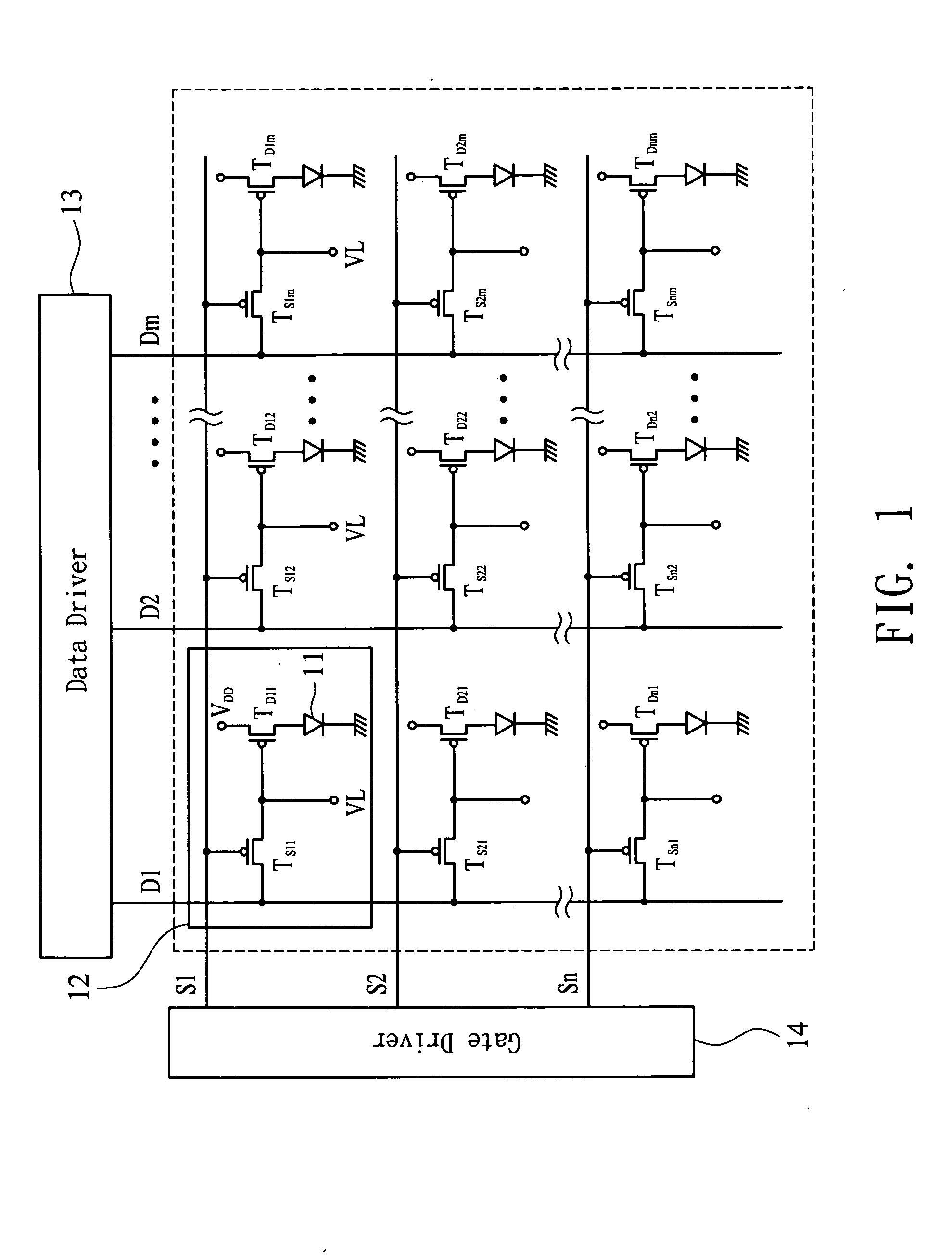
[0010]The present invention provides a passive matrix organic light emitting diode display device, which is composed of a plurality of vertical organic light emitting transistors. Since the vertical organic light emitting transistor is constructed by vertically integrating a transistor

Problems solved by technology

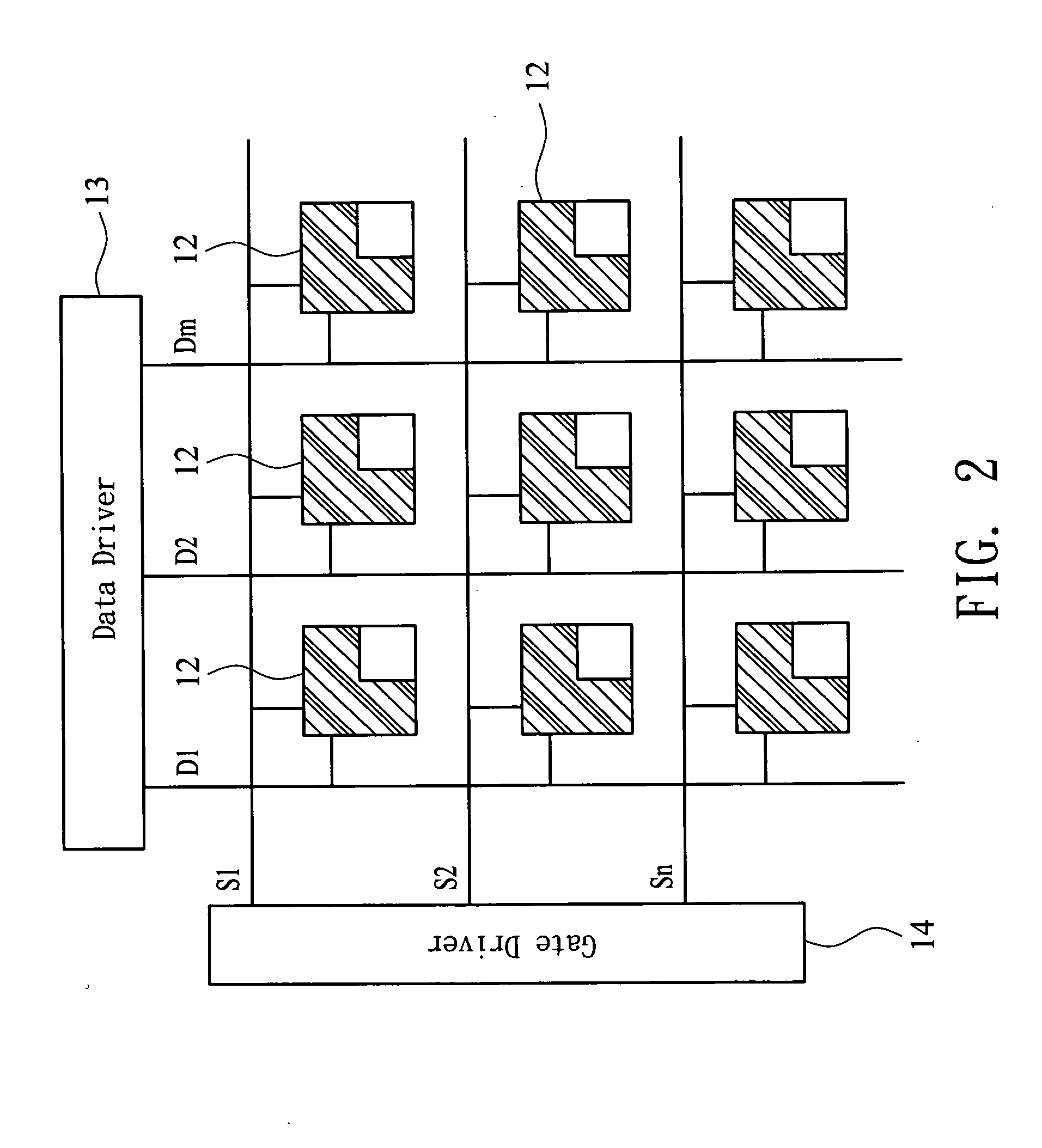
To state briefly, the conventional organic light emitting diode display device suffers a limitatio

Method used


Image

  • Passive matrix organic light emitting diode display device
  • Passive matrix organic light emitting diode display device
  • Passive matrix organic light emitting diode display device

Examples


Example

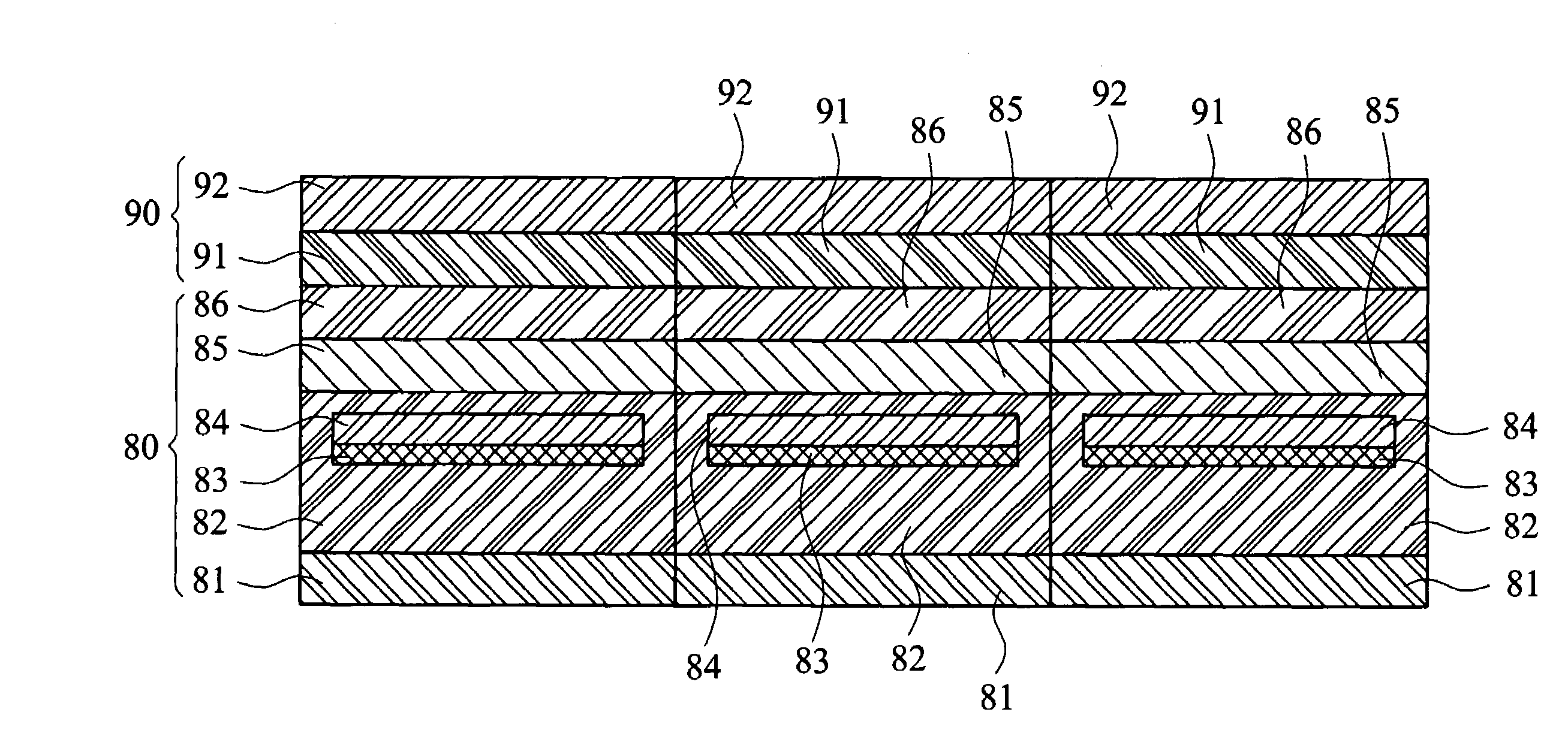
[0027]As illustrated in FIG. 3, a passive matrix organic light emitting diode display device according to a first embodiment of the present invention comprises a plurality of vertical organic light emitting transistors 20, each having a first collector 21, a first grid / base 22, and a first emitter 23. Therein, the plural vertical organic light emitting transistors 20 are crisscrossed into a matrix. As shown in FIG. 3, the display device comprises a matrix constructed from 3×3 vertical organic light emitting transistors 20.

[0028]The first collectors 21 of the vertical organic light emitting transistors 20 placed in a same column are electrically connected to form a plurality of first scan units 30 that are mutually parallel. The first grids 22 or the first bases 22 of the vertical organic light emitting transistors 20 placed in a same row are electrically connected to form a plurality of second scan units 40 that are mutually parallel. Similarly, the first emitters 23 of the vertical...


PUM


Abstract

A passive matrix organic light emitting diode display device comprises a plurality of vertical organic light emitting transistors, each having a first collector, a first grid/base, and a first emitter. Therein, the first collectors are electrically connected and arranged parallelly to form a plurality of first scan units, and the first grids/bases are electrically connected and arranged parallelly to form a plurality of second scan units, while the first emitters are integrated into a common electrode, in which the first scan units and the second scan units are perpendicularly crossed. By perpendicularly combining vertical transistors onto organic light emitting diodes so as to drive the organic light emitting diodes, an active area as well as a luminance of the organic light emitting diode display device are enhanced and consequently an aperture ratio of each pixel unit in the organic light emitting diode display device is increased.

Description

BACKGROUND OF THE INVENTION[0001]1. Technical Field[0002]The present invention relates to passive matrix organic light emitting diode (PMOLED) display devices. More particularly, the present invention relates a PMOLED display device constructed of a matrix of vertical organic light emitting transistors.[0003]2. Description of Related Art[0004]As one of the most promising flat panel display devices of nowadays, the organic light emitting diode (OLED) display device adopts a light emitting principle different from that of the prior liquid crystal display device, which uses liquid crystals as an optical switching medium. That is because of that liquid crystals do not naturally emit light and thus need a backlight source and an external electric voltage applied thereon to rotate the liquid crystals and manage the light transmission rate of the backlight source. Differently, the organic light emitting diodes emit light when receiving an electric current and need no additional backlight s...

Claims


Application Information

Patent Timeline
IPC IPC(8): H01L51/52G09F9/30G09G3/20G09G3/30H01L27/32H01L33/08H01L33/26H01L33/36H01L33/38H01L33/42H01L51/50
CPCH01L27/3288H01L51/5203H01L51/057H10K59/179H10K10/491H10K59/805H10K50/805
Inventor MENG, HSIN-FEIHORNG, SHENG-FUCHAO, YU-CHIANG
Owner NATIONAL CHIAO TUNG UNIVERSITY
Why Eureka
Try Eureka