
Flat type vibration motor with increased vibration amount

a vibration motor and vibration amount technology, applied in the direction of dynamo-electric machines, electrical equipment, supports/enclosements/casings, etc., can solve the problems of increasing eccentric weight, reducing the magnetic flux provided to the motor, and increasing the eccentric weight, so as to increase the vibration amount of the motor, reduce the total size of the motor, and increase the size of the vibrator

Inactive Publication Date: 2009-09-17
BYD CO LTD
View PDF9 Cites 4 Cited by
  • Summary
  • Abstract
  • Description
  • Claims
  • Application Information

AI Technical Summary

Benefits of technology

[0009]The object of the present invention is to ensure that the vibration amount of a flat type vibration motor will not be reduced severely as the motor size is reduced, and simplify the motor manufacturing process and provide a flat type vibration motor with increased vibration amount.
[0015]The surface of the vibrator is nickel-plated, so as to increase magnetic conductibility at the center of the winding coils, and magnetic conductibility between the winding coils and the magnet.
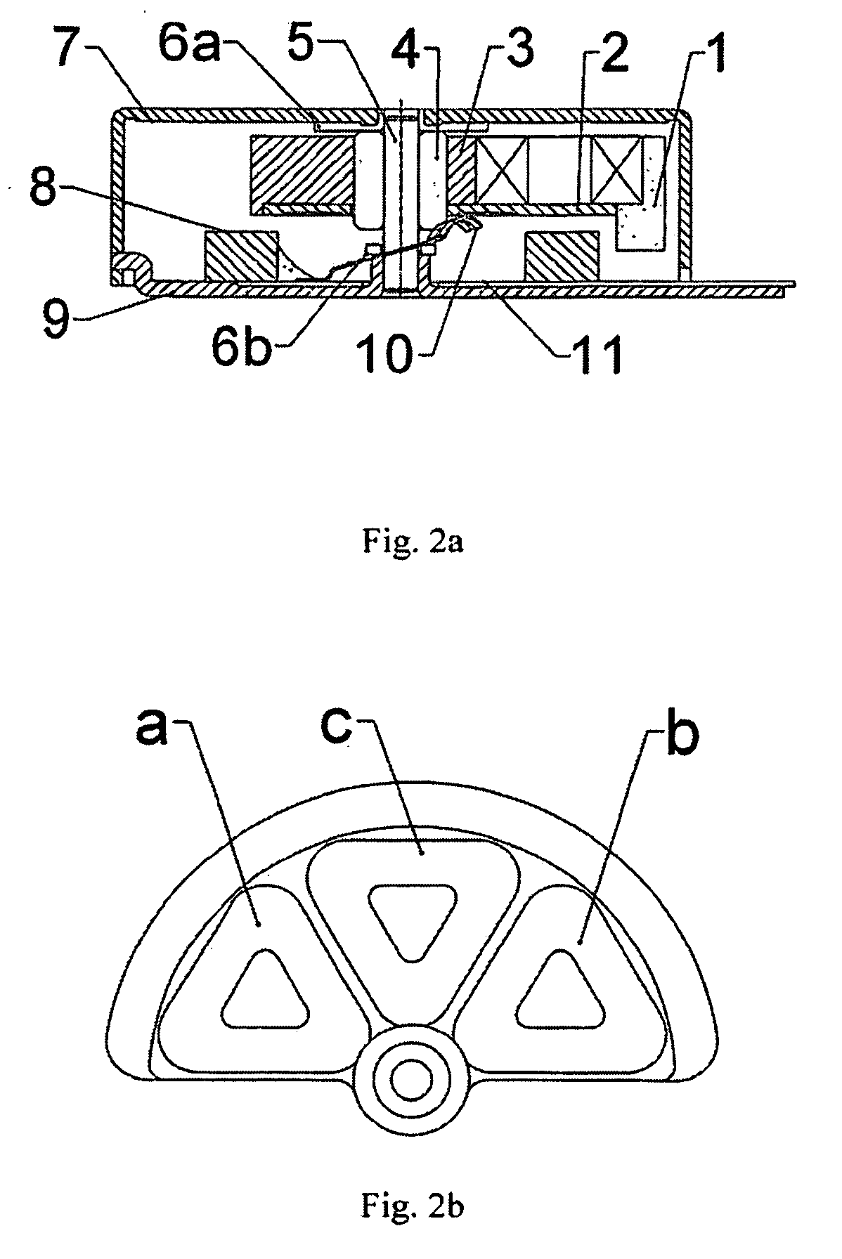
[0018]With the above technical solution, the winding coils and the hard circuit board are mounted to the vibrator firstly to form a special vibrator, and then the special vibrator with the winding coils and the hard circuit board is injection molded into the rotor. Since the winding coils and the hard circuit board are mounted on the vibrator, they will no longer be factors for blocking the vibrator to extend outwards, and therefore the outer edge of the vibrator can be extended to a position beyond the winding coils and the hard circuit board. To this end, the size of the vibrator can be increased while the total size of the motor is reduced, and thereby the vibration amount of the motor can be increased. In addition, the performance of the magnet and winding coils is not affected.

Problems solved by technology

In the second technical solution described above, since the eccentric weight is provided by the composite engineering plastic, the increase of eccentric weight is limited, and the size of the magnet has to be reduced greatly due to the protruding part of the rotor; as a result, the magnetic flux provided to the motor is reduced significantly, and the motor performance will be degraded severely.
Though the third technical solution can increase the eccentric amount to a certain degree, the increase in the size of the vibrator is very limited.
All the technical solutions described above have the drawbacks in that: the vibration amount will be reduced severely as the motor size is reduced; before the motor rotor is injection molded, the winding coils and the eccentric vibrator must be fixed by bonding, thus they may displace when the rotor is injection molded if they are not fixed well.

Method used


Image

  • Flat type vibration motor with increased vibration amount
  • Flat type vibration motor with increased vibration amount
  • Flat type vibration motor with increased vibration amount

Examples


Embodiment Construction

[0031]Hereinafter, the present invention will be described with some embodiments, with reference to the accompanying drawings 4a-6b, wherein identical reference numbers designate identical or similar components in the accompanying drawings.

[0032]The flat type vibration motor provided in the present invention comprises an end cap assembly with a power input and transfer unit, a rotor that rotates and produces eccentric vibrations, and a stator composed of an upper case and sliding blades. The stator part comprises an upper case and sliding blades that are bonded to the center of the upper case and protrude from the circular part and are designed to reduce vibration and friction. The end cap assembly comprises a lower case, a flexible circuit board bonded to the lower case for receiving electrical power, a brush welded to the flexible circuit board, a shaft pressed into the center of the end cap, and gaskets fitted over the shaft below the rotor. The rotor part is based on a vibrator ...


PUM


Abstract

A flat type vibration motor with increased vibration amount comprises a vibrator (1), a hard circuit board (2), a rotor (3), a shaft (5), a lower case (9), a magnet (8), a flexible circuit board (11), a brush (10) and winding coils (a, b). The rotor (3) is formed by injection-molding the vibrator (1). The winding coils (a, b) and the hard circuit board (2) are both mounted on the vibrator (1), thus the outer edge of the vibrator (1) can be extended to the position beyond the winding coils (a, b) and the hard circuit board (2).

Description

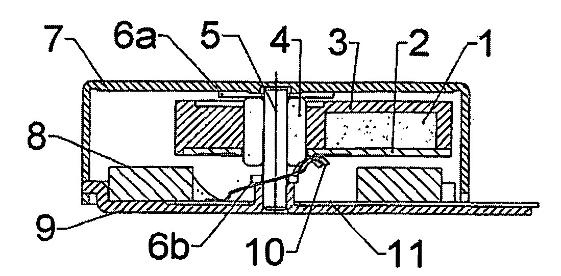
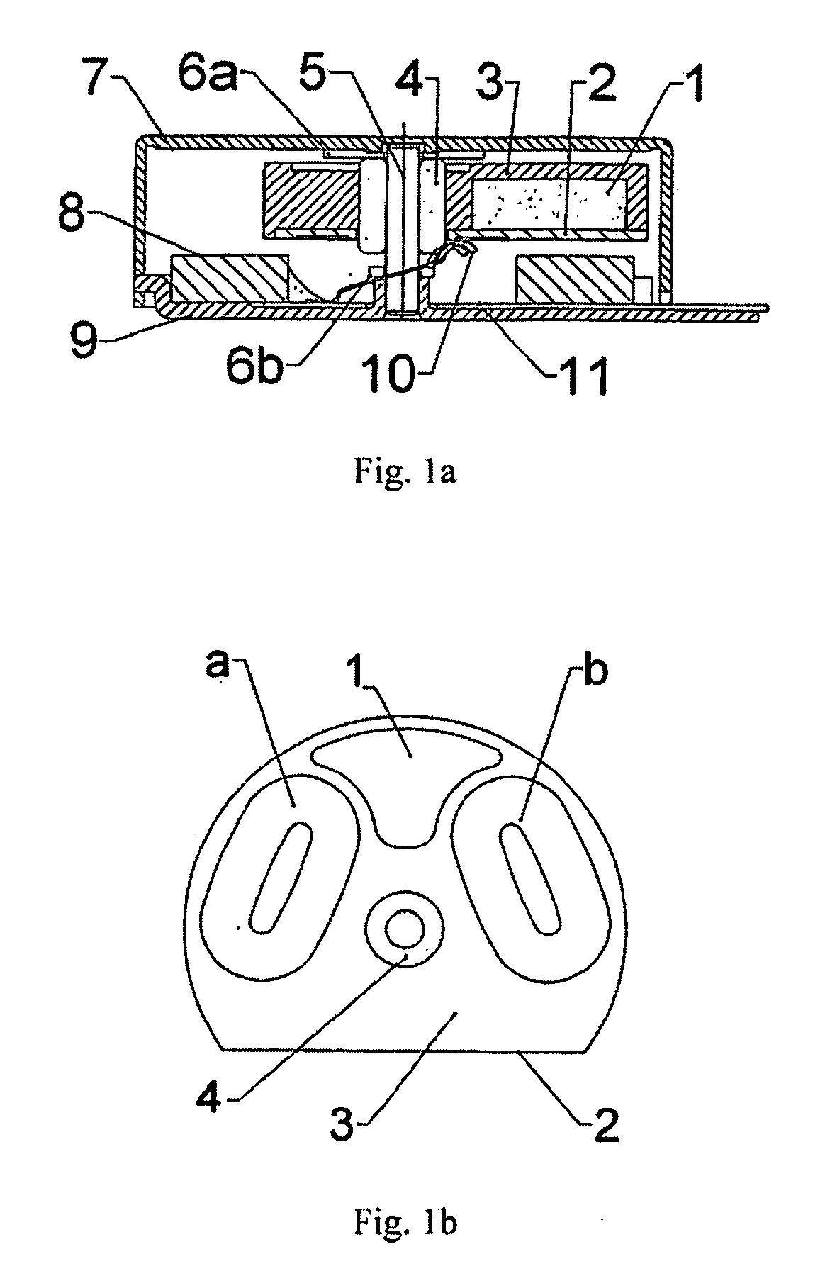
FIELD OF INVENTION[0001]The present invention relates to a DC permanent magnetic vibration motor applicable to communication devices such as mobile telephones and Beep Pagers (BBs), which is a flat type vibration motor that can produce vibrations to prompt or warn the user in receipt of signals in occasions that the ringing is unsuitable.BACKGROUND OF INVENTION[0002]The structure of a flat type vibration motor in the prior art is shown in FIG. 1a and 1b, wherein, an eccentric vibrator 1 and winding coils a, b are bonded to a circuit board 2 with glue, and then are injection-molded with a center oil-retaining bearing 4 together to form a rotor 3; the center shaft 5 is fixed on a lower case 9, the rotor is mounted on the shaft through the bearing hole, and a magnet 8 is bonded to the lower case 9 to provide magnetic flux. A brush 10 is welded to a flexible circuit board 11, an upper case 7 covers the rotor and the lower case, and gaskets 6a, 6b are mounted on top side and bottom side ...

Claims


Application Information

Patent Timeline
Patent Type & Authority Applications(United States)
IPC IPC(8): H02K7/075
CPCH02K3/47H02K5/1677H02K23/04H02K7/063H02K7/065
Inventor ZHAO, KELONGWU, XUEZHONG
Owner BYD CO LTD
Learn More