Rear surface projection type image display device

a projection type, image display technology, applied in the direction of television systems, panoramic photography, instruments, etc., can solve the problems of difficult to have a maximum gain at the front side of the projector, peripheral luminance becomes darker than the central luminance, and may easily reflect the shadow of an observer on the screen, so as to prevent the unevenness of luminance, prevent the attenuation of luminance, and high diffusion

Inactive Publication Date: 2009-09-17
SONY CORP
View PDF9 Cites 14 Cited by
  • Summary
  • Abstract
  • Description
  • Claims
  • Application Information

AI Technical Summary

Benefits of technology

[0053]With the present invention, the excellent rear projection type image display apparatus can be provided, which has the large half-power angle of the gain through the rear transmission, and can obtain diffusion in the wider range, so as to prevent the unevenness of luminance depending on the location of an image on the transmission type screen and to prevent the attenuation in luminance when the image is viewed from a position other than the front side.
[0054]Also, with the present invention, the excellent rear projection type image display apparatus can be provided, which has the larger half-power angle and can properly block a direct light from the projector for the observer.
[0055]Also, with the present invention, since the rear projection type screen employs the screen having the larger half-power angle, high diffusion, and wide viewing characteristic, the excellent rear projection type image display apparatus can be provided, which can enlarge the projection region while preventing the change in color or the unevenness of the luminance when the multi-projection is applied.
[0056]With the rear projection type image display apparatus according to the present invention, by performing the diffusion at the scree

Problems solved by technology

In the front projection type, if a picture is enlarged, there is a problem that the shadow of an observer may be easily reflected on the screen.
However, since the projection light is divergently incident and the peripheral portion has the outward directional property, when being observed from the front side of the screen, there is a problem that the peripheral luminance becomes darker than the central luminance.
Even though a diffusing plate is provided in the path of the projection light, or the projection screen itself is constituted by a diffusing plate for diffusing the light beam, which has formed an image, in various directions to equalize the luminance, it is difficult to have a maximum gain at the front side of the projector and to avoid generating a phenomenon that a gain becomes small as an angle increases with respect to a light beam direction with the maximum gain obtained.
In other words, through the rear projection, even though a diffusing plate for simple diffusion is used, it is difficult to perform perfect diffusion, causing a high front gain.
Having a small half-power angle means that the amount of attenuation in luminance becomes radical when an image is viewed from a position other than the front side

Method used


Image

  • Rear surface projection type image display device
  • Rear surface projection type image display device
  • Rear surface projection type image display device

Examples


first embodiment

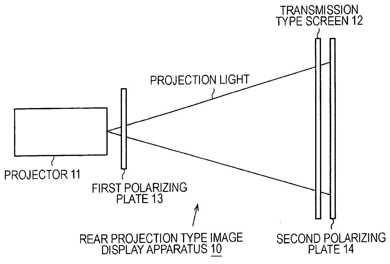
[0097]FIG. 1 schematically shows a configuration of an image display apparatus according to the present invention. The illustrated image display apparatus is a rear projection type image display apparatus that performs image formation with an illumination light from a projector on a screen to display an image, and more specifically, is a rear projection type image display apparatus that enlarges and projects a small, high luminance image emitted from a projector on a rear surface of a transmission type screen viewed by an observer. The region may be enlarged, for example, by arranging projectors in an array.

[0098]This rear projection type image display apparatus 10 includes a projector 11 that projects an image having a relatively high luminance, a transmission type screen 12 installed at an image formation plane of a projection light from the projector 11, and a direct light blocking portion provided for blocking a direct light from the projector and composed of a first polarizing ...

second embodiment

[0126]FIG. 10 schematically shows a configuration of an image display apparatus according to the present invention. The illustrated image display apparatus 20 is rear projection type, and constituted by a projector 21 that projects an image having a relatively high luminance, and a rear projection purpose screen 22 installed at an image formation plane of a projection light from the projector 21.

[0127]The rear projection purpose screen 22 has a double-layer screen configuration of a matt screen 22A arranged on the viewer side as described above, and a screen 22B arranged on the projector 21 side and made of a fibrous texture, thereby achieving the widening of the viewing angle. If the two screens are sufficiently closely attached, an image can be projected without defocusing. Also, if the two screens are separated by a proper distance, the difference between the colors of the projector 21 can be further reduced, and the image can be defocused.

[0128]The matt screen 22A diffuses the i...


PUM


Abstract

A rear projection type image display apparatus having a larger half-power angle and being capable of properly blocking a direct light from a projector for an observer is provided.
The rear projection type image display apparatus includes a projector and a transmission type screen installed at an image formation plane of a projection light and made of a texture. The screen made of the texture is a diffusing material having a large half-power angle except for the direct light, and can prevent a gain from being decreased even at an angle of 60 degrees or larger. Also, a first polarizing plate is arranged in front of an exit pupil of the projector, and a second polarizing plate is arranged near a rear surface of the transmission type screen. Polarization axes of these polarizing plates are configured to be substantially orthogonal to each other, to eliminate the direct light.

Description

TECHNICAL FIELD[0001]The present invention relates to an image display apparatus that performs display output of a large picture, and more particularly to a projection type image display apparatus that performs display output of a large picture by projecting a picture on a screen with the use of a projector.[0002]Further particularly, the present invention relates to a rear projection type image display apparatus that diffuses a high luminance projection light from a projector at a transmission type screen installed at an image formation plane thereof to form an observable image, and more particularly to a rear projection type image display apparatus that has a larger half-power angle and blocks a direct light from a projector for an observer.BACKGROUND ART[0003]Such as a television receiver, image display apparatuses like a CRT (Cathode Ray Tube) display and a LCD (Liquid Crystal Display) have been widely spread. In recent years, demands on large pictures for home theater purpose m...

Claims


Application Information

Patent Timeline
IPC IPC(8): G03B21/14G03B21/28G03B21/62G02F1/1335G02F1/13363G03B21/10H04N5/74
CPCG03B21/62H04N9/3197H04N9/3167G03B37/04
Inventor KONDO, TETSUJIROKOKUBO, TETSUSHIMUKAI, HITOSHIHIBI, HIROFUMITANAKA, KAZUMASATANAKA, KENJIMORISAKI, HIROYUKI
Owner SONY CORP
Why Eureka
Try Eureka