Rapid Microscope Scanner for Volume Image Acquisition

a volumetric scanner and scanner technology, applied in the field of optical microscopy, can solve the problems of inability to efficiently digitize volumetric specimens with two-dimensional scanners, difficult to ensure focus in microscope scanners, and thick volumetric structur

Active Publication Date: 2009-09-17
LEICA BIOSYST IMAGING
View PDF11 Cites 150 Cited by
  • Summary
  • Abstract
  • Description
  • Claims
  • Application Information

AI Technical Summary

Benefits of technology

[0013]Systems and methods are provided for rapid three dimensional scanning and digitizing of an entire microscope sample, or a substantially large portion of a microscope sample, using a tilted sensor synchronized with a positioning stage. The systems and methods also provide for interpolating tilted image layers into an orthogonal three dimensional array or into its two

Problems solved by technology

A problem commonly arises when the specimen has a thick volumetric structure.
On the other hand, it becomes increasingly difficult to ensure focus in microscope scanners with small depth of field as the thick specimen may have a significant depth variance within the field of view.
Consequently, such volumetric specimens cannot be digitized efficiently with two-dimensional scanners.
In particular, a thick specimen with a three dimensional structure or volume texture cannot be fully represented by its two dimensional image.
A linear array sensor typically used in scanning microscopes cannot capture optical images from different

Method used


Image

  • Rapid Microscope Scanner for Volume Image Acquisition
  • Rapid Microscope Scanner for Volume Image Acquisition
  • Rapid Microscope Scanner for Volume Image Acquisition

Examples


second embodiment

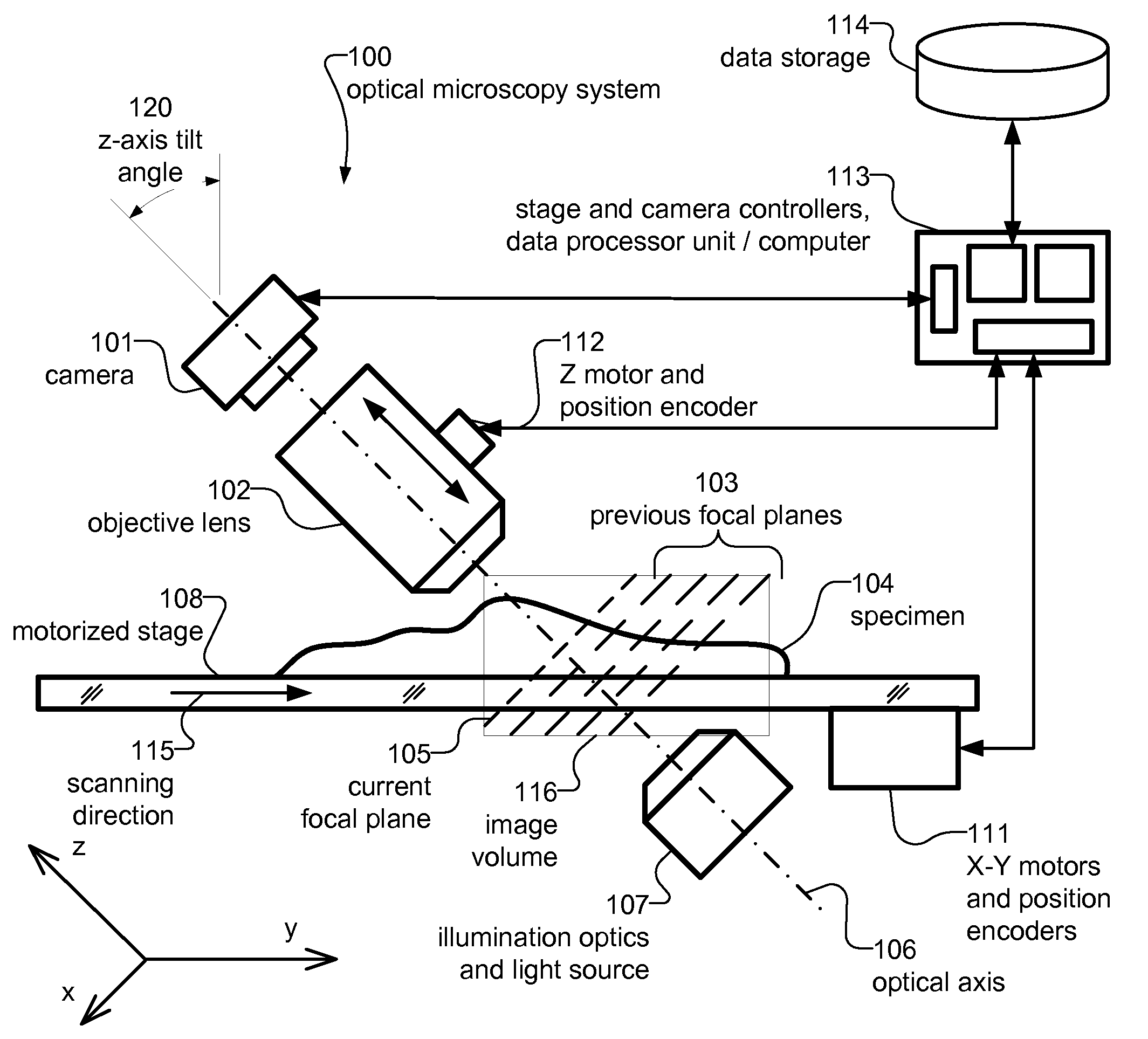
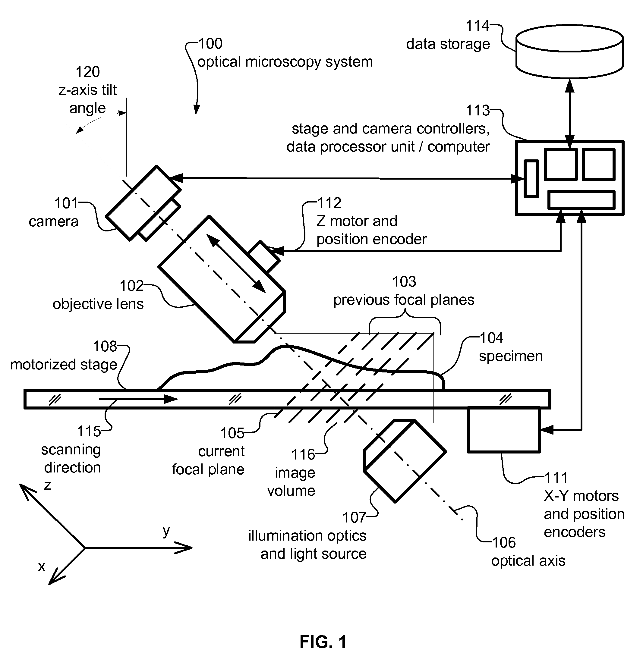
[0042]According to the present invention as illustrated in FIG. 2, the system 100 has the camera 101 tilted at certain angle 110 with respect to the main optical axis 106, which is orthogonal to the plane of the motorized stage 108. Though the lighting system 107 and the microscope objective lens 102 are configured to image the horizontal focal plane 105, the camera captures the light scattered at the effective tilted focal plane 115. Such design ensures high efficiency of the lighting system 107 and the microscope objective lens 102 as well as minimizes the internal reflections inside the sample 104 and its cover glass.

[0043]Turning to the embodiment illustrated in FIG. 3, the system 100 is equally suitable for detecting optical energy that is reflected from the sample 12, in which case the lighting system 107 and the microscope objective lens 102 are positioned to ensure that the angle of light and the angle of incidence are equal. The lighting system 107 and the microscope object...

fourth embodiment

[0044]FIG. 4 depicts a dual lens microscopy system operating according to a The two sets of cameras 101-A, 101-B, objective lenses 102-A, 102-B and illumination system 107-A, 107-B enable stereoscopic vision, by which every point of the sample 104 can be imaged from two different viewpoints and at two different angles. A three dimensional reconstruction can be implemented in the data processor unit combining image data from the two cameras.

[0045]Overall, the system 100 is suitable, with appropriate well-known modifications, for the interrogation of microscopic samples in any known mode of optical microscopy.

[0046]FIG. 5 illustrates alignment and interpolation processes from a tilted image stack 304 (input) into horizontal image stack 303 (output). This untilting process may be required to compress and to display the output image volume. The tilted image 306 captured by the camera 101 contains pixels or so called voxels 302 as the data is considered as a three dimensional volume. A ...


PUM


Abstract

Apparatus for and method of rapid three dimensional scanning and digitizing of an entire microscope sample, or a substantially large portion of a microscope sample, using a tilted sensor synchronized with a positioning stage. The system also provides a method for interpolating tilted image layers into a orthogonal tree dimensional array or into its two dimensional projection as well as a method for composing the volume strips obtained from successive scans of the sample into a single continuous digital image or volume.

Description

RELATED APPLICATION[0001]The present application claims priority to U.S. provisional patent application Ser. No. 60 / 916,240 filed May 4, 2007, which is incorporated herein by reference in its entirety.BACKGROUND[0002]1. Field of the Invention[0003]The invention relates generally to the field of optical microscopy, and in particular to an automatic microscope scanner enabling rapid three dimensional image acquisition.[0004]2. Related Art[0005]Automated microscope scanners such as disclosed in U.S. Pat. No. 6,711,283, which is incorporated herein in its entirety, enable rapid digitizing of an entire glass slide with a biological sample. These microscope scanners are particularly efficient when the sample thickness, i.e. the depth of the specimen on the glass is smaller or close to the depth of field of the microscope lens. The depth of field is the distance in front of and behind the theoretical focal plane where the specimen appears to be in focus.[0006]A problem commonly arises when...

Claims


Application Information

Patent Timeline
IPC IPC(8): G02B21/36
CPCG01B9/04G06K9/00134G02B21/367G06V20/693
Inventor PITTSYN, NIKOLAIEICHHORN, OLE
Owner LEICA BIOSYST IMAGING
Why Eureka
Try Eureka