Device and method for demodulating control signals

Inactive Publication Date: 2009-09-17
NEC CORP
View PDF2 Cites 9 Cited by
  • Summary
  • Abstract
  • Description
  • Claims
  • Application Information

AI Technical Summary

Benefits of technology

[0022]According to the present invention, it is possible to efficiently perform demodulation processing of r

Problems solved by technology

In such a case, if demodulation processing of control signals is performed by using a similar configuration that is used for demodulation processing of data signals, the processing cannot be pe

Method used


Image

  • Device and method for demodulating control signals
  • Device and method for demodulating control signals
  • Device and method for demodulating control signals

Examples


Example

[0029]1. Configuration

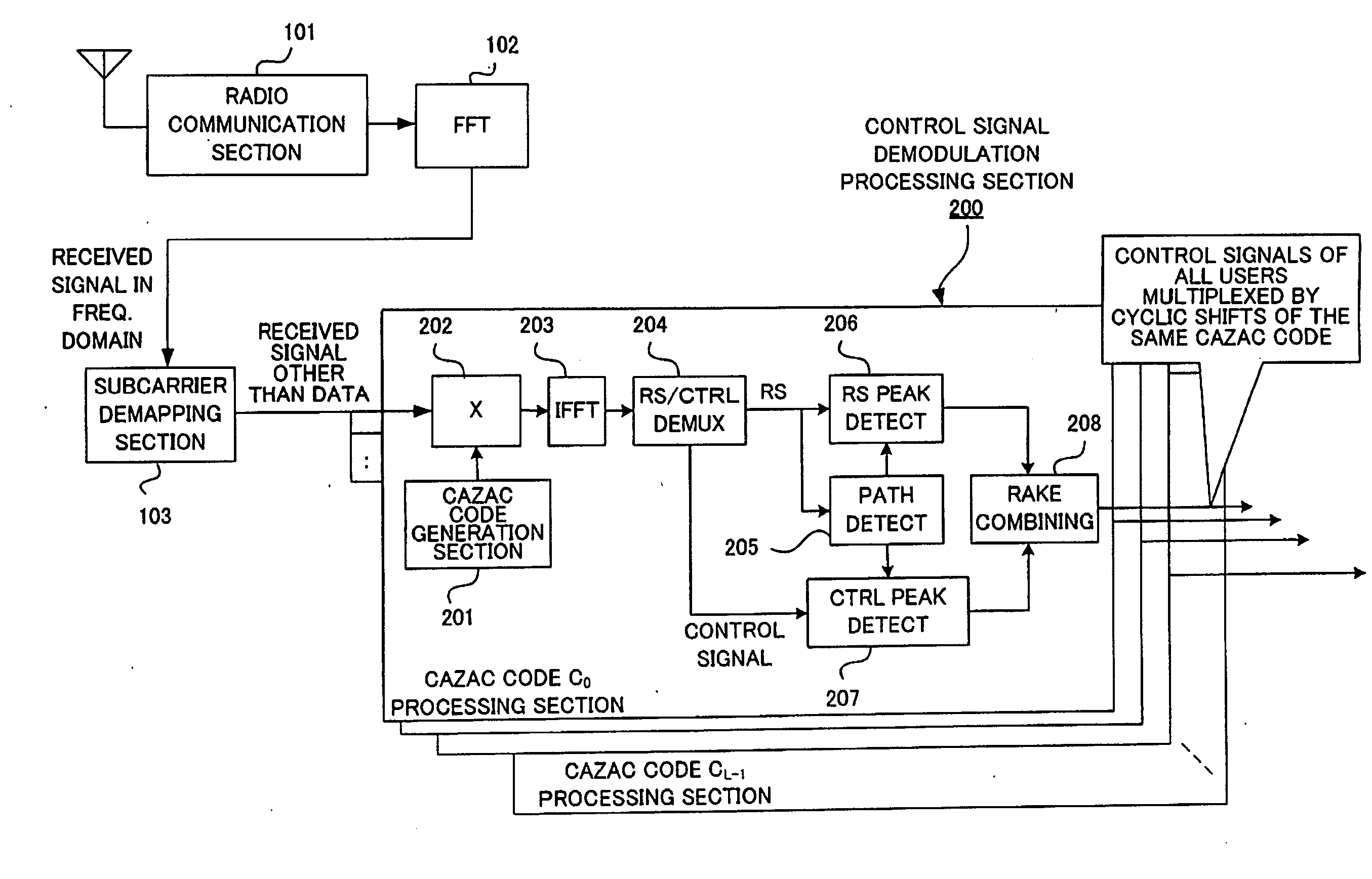
[0030]FIG. 4 is a block diagram showing a functional configuration of a radio communication device incorporating a control signal demodulation device according to an exemplary embodiment of the present invention. Here, it is assumed that a CAZAC code is used as a predetermined code, that a signal received by a radio communication section 101 is transformed into a frequency-domain representation by a fast Fourier transformer (FFT) 102, and that the frequency-domain received signal is input to a subcarrier demapping section 103. The subcarrier demapping section 103 extracts from the frequency-domain received signal those subcarriers that are assigned to control signals and reference signals other than data signals, and outputs the extracted subcarriers to a control signal demodulation processing section 200.

[0031]The control signal demodulation processing section 200 is composed of L separate control signal demodulation processing sections corresponding respectiv...


PUM


Abstract

A device performs demodulation of control signals from multiple radio terminals, based on the correlations in the frequency domain between a predetermined code and the orthogonalized control signals and reference signals of the multiple radio terminals obtained by cyclic shifts of the predetermined code. The device includes: a demultiplexer which demultiplexes a reference signal component and a control signal component based on a correlation profile; a path detector which detects a path location or path locations for each radio terminal based on the power values of the reference signal components; extractor which extracts the correlation values of the reference signal components and the correlation values of the control signal components, respectively; and RAKE combiner which combines the extracted values.

Description

[0001]This application is based upon and claims the benefit of priority from Japanese Patent Application No. 2008-063982, filed on Mar. 13, 2008, the disclosure of which is incorporated herein in its entirety by reference.BACKGROUND OF THE INVENTION[0002]1. Field of the Invention[0003]The present invention relates to a radio communications system and, more particularly, to a method and device for demodulating control signals in a radio communications system in which reference signals and control signals are transmitted according to code division multiplexing (CDM).[0004]2. Description of the Related Art[0005]The 3rd Generation Partnership Project (3GPP), which is a collaboration among organizations aiming to standardize radio communications systems, has been studying Long Term Evolution (LTE), which provides a high-speed, low-latency, and packet-optimized radio access technology, as a successor to current W-CDMA systems. In LTE, single-carrier transmission is adopted as the uplink a...

Claims


Application Information

Patent Timeline
IPC IPC(8): H04L27/06H04J13/18H04B1/707H04B1/7113H04B1/7115H04J11/00H04L27/01
CPCH04B1/7117H04J13/0059H04L5/0016H04L5/0048H04L25/022H04L27/2613H04L25/0228H04L27/2649H04L2025/03414H04L2025/03522H04L2025/03789H04L25/0226H04L27/26526H04L27/26H04W64/00
Inventor NAITO, KOSUKEIWASAKI, MOTOYA
Owner NEC CORP
Why Eureka
Try Eureka