Emergency core cooling system having core barrel injection extension ducts

a core cooling and core barrel technology, applied in the direction of nuclear reactors, nuclear elements, greenhouse gas reduction, etc., can solve the problems of unanticipated reactor core cooling effect, damage to the reactor, unexpected safety problems of pressurized light water reactors, etc., to prevent the level of cooling water from being lowered, reduce the cross flow resistance of the downcomer, and meet the safety and safety regulatory requirements of the reactor.

Inactive Publication Date: 2009-09-17
KOREA ATOMIC ENERGY RES INST +1
View PDF3 Cites 12 Cited by
  • Summary
  • Abstract
  • Description
  • Claims
  • Application Information

AI Technical Summary

Benefits of technology

[0027]According to the present invention, the emergency core cooling system having core barrel injection extension ducts prevents the phenomenon in which the emergency core cooling water is directly bypassed and discharged in the event of the LBLOCA and thus makes a larger quantity of emergency core cooling water contribute to the cooling of the core. Further, in the event of a direct vessel injection pipe line break, the emergency core cooling system having core barrel injection extension ducts has an effect of preventing the level of the cooling water from being lowered in the downcomer due to an inlet-outlet reverse phenomenon at the lowest position of the outlet of the injection extension duct.
[0028]Further, because the present invention features inclined lateral faces of the injection extension duct, which has a quadrilateral cross section in the prior art, the cross flow resistance of the downcomer is reduced. As a result of removing the connection structure between the direct vessel injection nozzle installed in the reactor vessel and the injection extension duct installed on the downcomer-side core barrel, the injection extension duct technology of the emergency core cooling water direct vessel injection system, which prevents an interference between the reactor vessel and the core barrel and a withdrawal interference for the neutron monitoring capsule, is provided, so that the safety and the safety regulatory requirements of the reactor can be sufficiently met.

Problems solved by technology

A pressurized light water reactor can encounter unexpected safety problems even though it has been designed in consideration of a sufficient safety margin.
If sufficient emergency core cooling water is not supplied when a safety problem in which a large quantity of cooling water leaks occurs, a core can overheat, resulting in damage to the reactor.
The cold leg injection type means that the emergency core cooling water is supplied to a reactor system through an injection line, which is connected to a cold leg corresponding to a pipe supplying cold water from the circulating pump of a reactor coolant circulatory system into the reactor vessel, and has a drawback in that, when the emergency core cooling water is supplied to a broken cold leg, the emergency core cooling water completely leaks out of the broken cold leg, and thus the reactor core cooling effect cannot be expected.
However, the direct vessel injection type has a problem in that there is an increase in the emergency core cooling water direct bypass phenomenon, in which, when the cold leg is broken, the emergency core cooling water is headed to the broken cold leg by strong cross-flow of the downcomer, and is discharged out of the reactor vessel.
When the reactor vessel is assembled with the core barrel, interference between the projections occurs.
However, when a DVI line itself is broken, an outlet of the injection extension duct 110 or 110′ functions as an inlet of a break flow due to a siphon effect, and the level of the cooling water in the reactor vessel is lowered by the length of the injection extension duct 110 or 110′, so that the core cladding temperature is abnormally increased.
This leads to a problem of noncompliance with safety regulations.
However, this conventional technology also has a problem in that, when the reactor vessel is assembled with the core barrel 200, interference between the nozzles 230 and 230′ protruding to the downcomer 240 occurs, thus making an assembly difficult, and thus a hole, which is used for a periodical withdrawal checkup of a neutron monitoring capsule installed at a lower portion of the reactor vessel, overlaps with the protruding nozzles, so that work becomes impossible.
As such, there is a problem in that the level of the cooling water in the reactor vessel is significantly lowered down to the lowest outlet of the injection extension duct 210, and then the lowest outlet of the injection extension duct 210 functions as an inlet.
This has a lethal result when the reactor core is cooled.
As described above, the conventional common technical problem is mostly attributable to a connection structure in which the DVI nozzle and the injection extension duct are connected to each other in the downcomer.

Method used


Image

  • Emergency core cooling system having core barrel injection extension ducts
  • Emergency core cooling system having core barrel injection extension ducts
  • Emergency core cooling system having core barrel injection extension ducts

Examples


Embodiment Construction

[0036]Reference will now be made in greater detail to an exemplary embodiment of the invention, an example of which is illustrated in the accompanying drawings. Wherever possible, the same reference numerals will be used throughout the drawings and a description to refer to the same or like parts. The detailed descriptions of known functions and constructions that might needlessly obscure the subject matter of the present invention will be avoided herein.

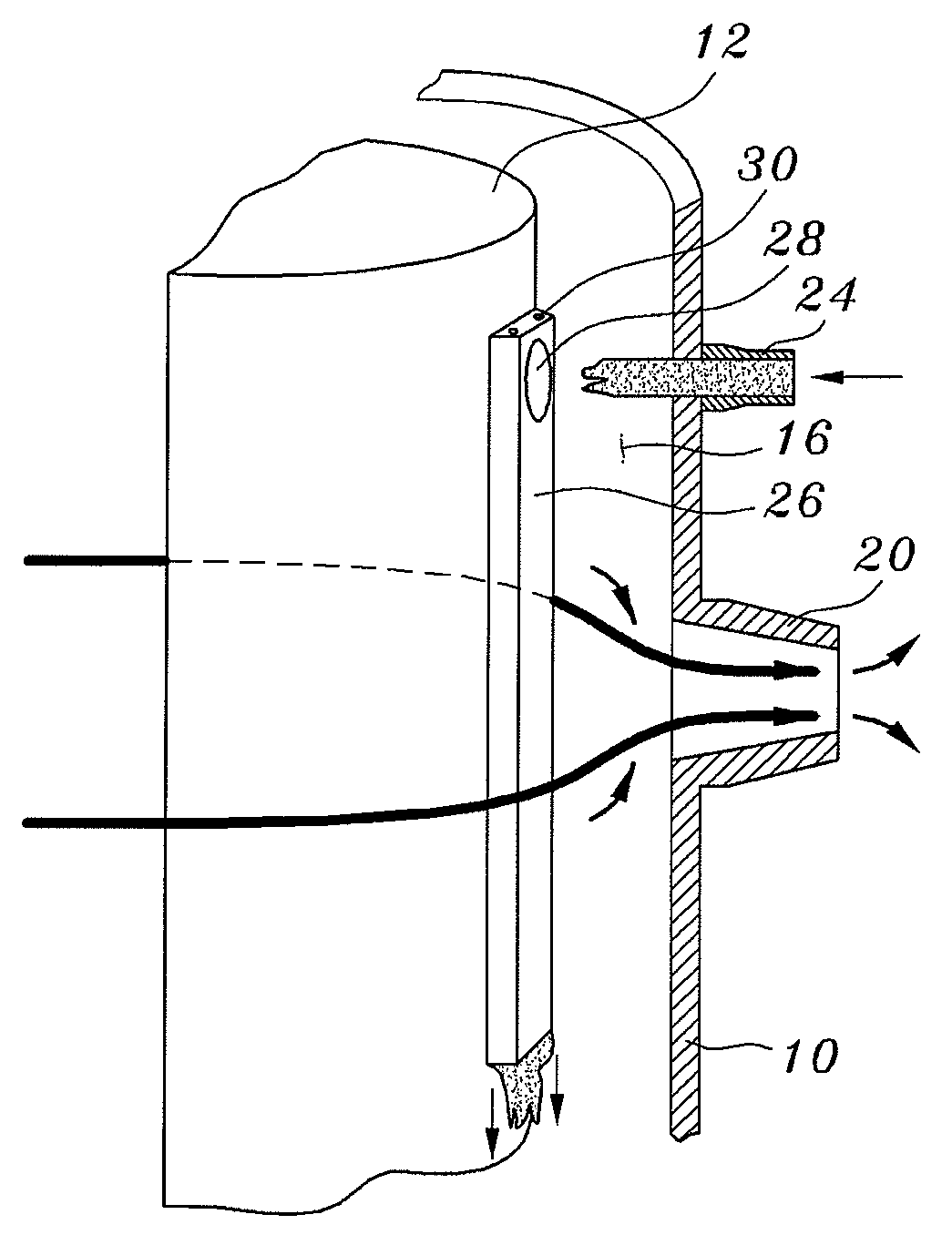
[0037]As illustrated in FIG. 4A, an emergency core cooling system having injection extension ducts 26 of a core barrel 12 adopts a system of directly injecting emergency core cooling water into the downcomer 16 of a reactor vessel 10. Here, a pressurized light water reactor generally comprises an outer reactor vessel 10 and a core barrel 12, which has a diameter smaller than that of the reactor vessel 10 and is installed at the center of the reactor vessel 10. Further, a core 14 into which nuclear fuel rods are charged is located in...


PUM


Abstract

An emergency core cooling system directly injects emergency core cooling water, which is supplied from a high-pressure safety injection pump or a safety injection tank for a pressurized light water reactor, into a reactor vessel downcomer. A pipe connector is completely removed from between each direct vessel injection nozzle and each injection extension duct installed on an outer surface of the core barrel, which are opposite to each other. An emergency core cooling water intake port, through which the water is injected from each direct vessel injection nozzle, is formed on the surface of each injection extension duct facing an axis of each direct vessel injection nozzle. Thereby, a structure in which a jet of the emergency core cooling water flows into the injection extension ducts is adopted in a hydraulic connection fashion.

Description

BACKGROUND OF THE INVENTION[0001]1. Field of the Invention[0002]The present invention relates generally to an emergency core cooling system (ECCS) for a pressurized light water reactor, which directly injects emergency core cooling water, which is supplied from a high-pressure safety injection pump or a safety injection tank, into the downcomer of a reactor vessel, and, more particularly, to a downcomer injection extension duct technology for interrupting an emergency core cooling water direct bypass discharge phenomenon in which emergency core cooling water is guided by a strong cross-flow of the downcomer in the event of a large break loss of coolant accident (LBLOCA), and is then discharged out of the reactor.[0003]2. Description of the Related Art[0004]A pressurized light water reactor can encounter unexpected safety problems even though it has been designed in consideration of a sufficient safety margin. If sufficient emergency core cooling water is not supplied when a safety p...

Claims


Application Information

Patent Timeline
Patent Type & Authority Applications(United States)
IPC IPC(8): G21C9/00
CPCG21C15/18G21C15/182G21Y2002/201Y02E30/40G21Y2002/302G21Y2002/50G21Y2004/302G21Y2002/207Y02E30/30
Inventor KWON, TAE-SOONSONG, CHUL-HWABAEK, WON-PIL
Owner KOREA ATOMIC ENERGY RES INST
Why Eureka
Try Eureka