Piezoelectric micro-blower

Active Publication Date: 2009-09-17
MURATA MFG CO LTD
View PDF4 Cites 110 Cited by
  • Summary
  • Abstract
  • Description
  • Claims
  • Application Information

AI Technical Summary

Benefits of technology

[0009]An object of preferred embodiments of the present invention is to provide a piezoelectric micro-blower cap

Problems solved by technology

However, when a micropump with such check valves is used for conveying compressive fluid, such as air, the amount of displacement of the piezoelectric element is very small and fluid can be hardly

Method used


Image

  • Piezoelectric micro-blower
  • Piezoelectric micro-blower
  • Piezoelectric micro-blower

Examples


first embodiment

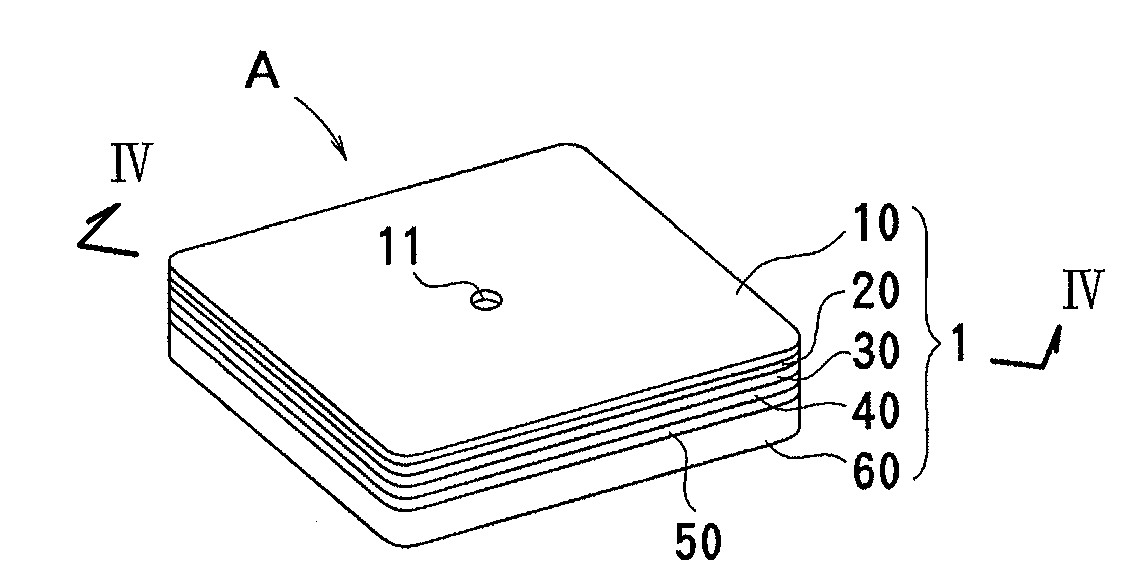
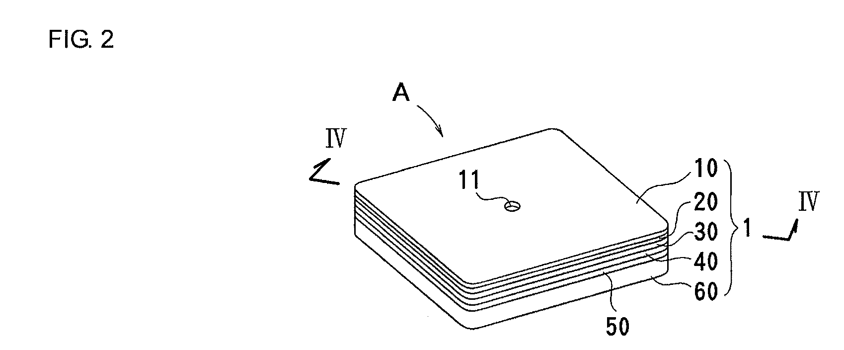
[0053]FIG. 2 to FIG. 5 illustrate a piezoelectric micro-blower according to a first embodiment of the present invention. A piezoelectric micro-blower A of the present embodiment is used as an air cooling blower for an electronic device. The piezoelectric micro-blower A includes, in order from the top, a top plate (second wall) 10, a flow path plate 20, a separator (first wall) 30, a blower frame 40, a diaphragm 50, and a bottom plate 60 that are stacked and secured together. The perimeter of the diaphragm 50 is bonded and secured between the blower frame 40 and the bottom plate 60. The above-described components except the diaphragm 50, that is, the components 10, 20, 30, 40, and 60 constitute the blower body 1 and are metal or hard resin plates formed of flat sheet materials having high stiffness.

[0054]The top plate 10 is a rectangular flat plate having an outlet (second opening) 11 at the center thereof. The outlet 11 penetrates the top plate 10 from the front surface to the back ...

second embodiment

[0073]FIG. 9 illustrates a micro-blower according to a second embodiment of the present invention. In the second embodiment, parts identical to those of the first embodiment are given the same symbols, and redundant description will be omitted. In the micro-blower B of the present embodiment, an annular piezoelectric element 52a having a hollow at its center is used as a piezoelectric element. Then, the perimeter of the piezoelectric element 52a is disposed near the blower body 1 holding the perimeter of a diaphragm 50b.

[0074]FIGS. 10(a) and 10(b) show how the diaphragm including the disk-shaped piezoelectric element and the diaphragm including the annular piezoelectric element are displaced in the third-order resonance mode. When the disk-shaped piezoelectric element 52 is used, as illustrated in FIG. 10(a), the piezoelectric element extends from the center position (0 mm) to the position of 6 mm. When the annular piezoelectric element 52b is used, as illustrated in FIG. 10(b), th...

third embodiment

[0078]FIG. 11 to FIG. 13 illustrate a micro-blower according to a third embodiment of the present invention. In the third embodiment, parts identical to those of the first embodiment are given the same symbols, and redundant description will be omitted. In a micro-blower D of the present embodiment, a rectangular center space 23 serving also as an inflow path is formed in the center of the flow path plate 20. The center space 23 has an opening area greater than that of the hollow 41 of the blower frame 40, the hollow 41 constituting the blower chamber 4. The separator (first wall) 30, the blower frame 40, the bottom plate 60, and the diaphragm 50 are provided with notches 33, 43, 63, and 51b, respectively, at their two diagonal corners. These notches correspond to corners of the center space 23 and form the inlets 8. The bottom plate 60 is provided with a slit 64. When the micro-blower D is mounted on a substrate or the like, the slit 64 serves as a vent for preventing the space und...


PUM


Abstract

A piezoelectric micro-blower capable of efficiently conveying compressive fluid without use of a check valve and ensuring a sufficient flow rate. The micro-blower has a blower body with a first wall and a second wall. Openings are formed in the respective walls and face a center of a diaphragm. An inflow path allowing the openings to communicate with the outside is formed between the walls. By applying a voltage to a piezoelectric element to cause the diaphragm to vibrate, a part of the first wall close to the first opening vibrates. Thus, gas can be drawn from the inflow path and discharged from the opening in the second wall.

Description

CROSS REFERENCE TO RELATED APPLICATIONS[0001]The present application is a continuation of International Application No. PCT / JP2007 / 073571, filed Dec. 6, 2007, which claims priority to Japanese Patent Application No. JP2006-332693, filed Dec. 9, 2006, and Japanese Patent Application No. JP2007-268503, filed Oct. 16, 2007, the entire contents of each of these applications being incorporated herein by reference in their entirety.FIELD OF THE INVENTION[0002]The present invention relates to a piezoelectric micro-blower suitable for conveying compressive fluid, such as air.BACKGROUND OF THE INVENTION[0003]A piezoelectric micropump is used as a cooing-water conveying pump for compact electronic devices, such as notebook computers, and also as a fuel conveying pump for fuel cells. On the other hand, a piezoelectric micro-blower is used as an air blower serving as an alternative to a cooling fan for a CPU etc., and is also used as an air blower for supplying oxygen necessary for generating e...

Claims


Application Information

Patent Timeline
IPC IPC(8): F04B43/04
CPCF04B43/046F04B53/1077F04B45/047F04B45/04F04B53/10F04B53/06F04B53/16F05B2210/12F04B2201/0806Y10S417/00
Inventor HIRATA, ATSUHIKOKAMITANI, GAKUWADA, HIROAKISUNAGA, MIDORIKANAI, SHUNGO
Owner MURATA MFG CO LTD
Why Eureka
Try Eureka