
Floor sanding sponge pads

a sponge pad and floor technology, applied in the field of floor sanding sponge pads, can solve the problems of difficult intercoat adhesion in the subsequent application of the coating, several problems for users, and the combination of two products is problematic, so as to prolong the life of the product, improve the appearance of the floor surface, and soften the scratch pattern. fine

Inactive Publication Date: 2009-09-17
SAINT GOBAIN ABRASIVES INC +1
View PDF29 Cites 6 Cited by
  • Summary
  • Abstract
  • Description
  • Claims
  • Application Information

AI Technical Summary

Benefits of technology

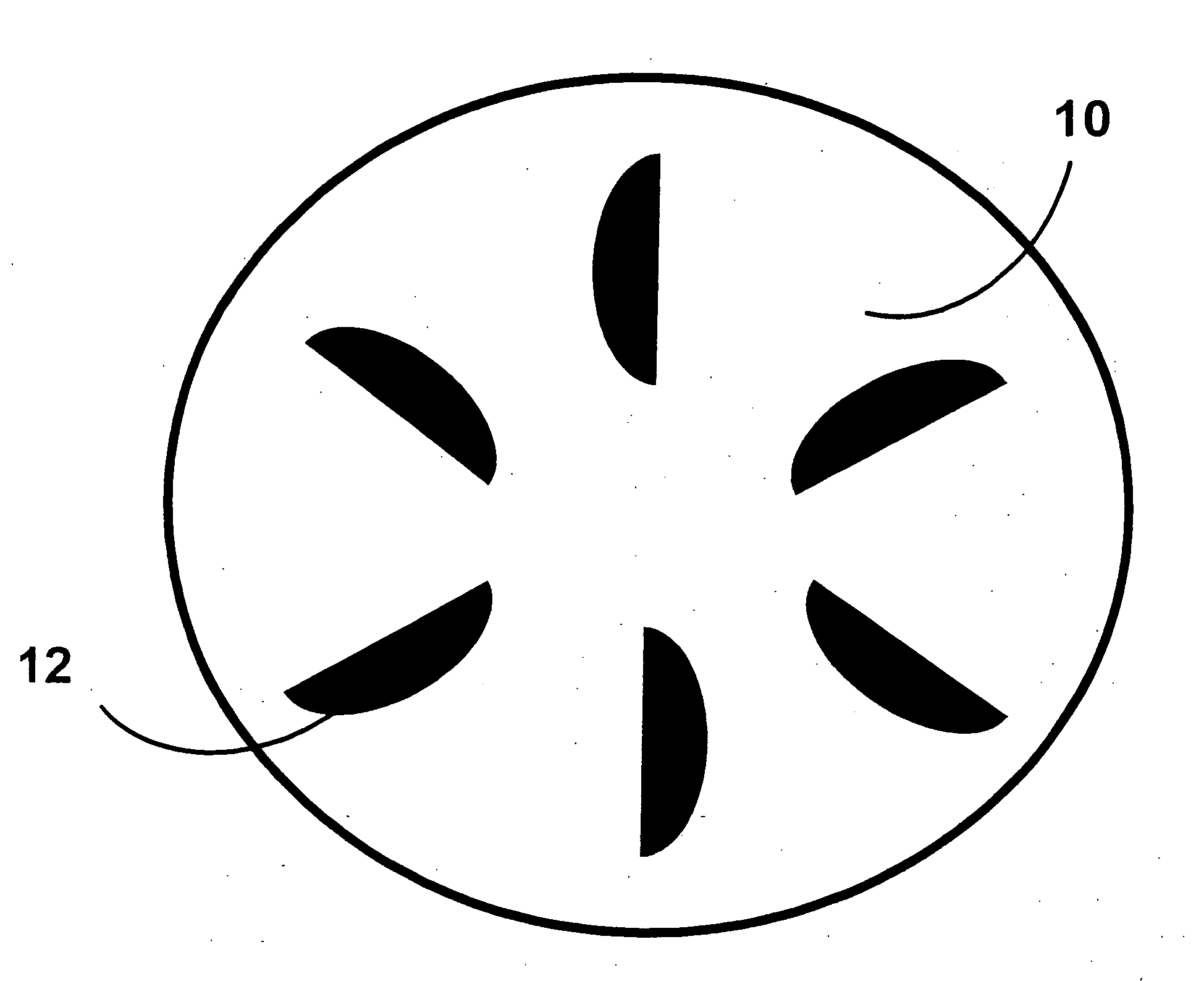
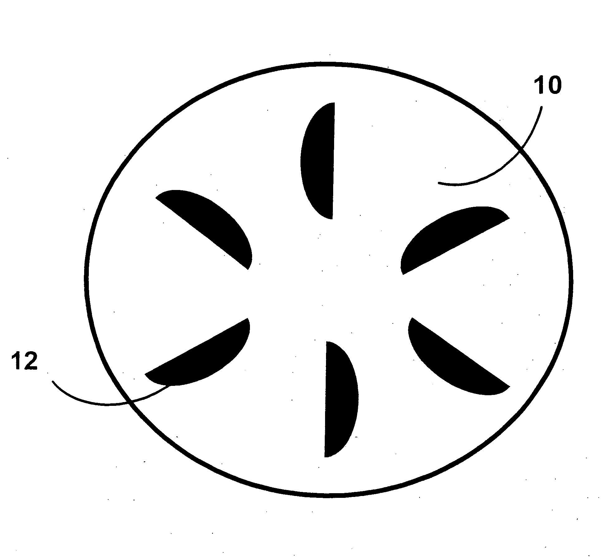
[0014]Many benefits result in the floor sanding sponge disclosed herein. First, the floor sanding sponge disclosed herein will perform the duty of both the nylon non-woven pad / coated abrasive in one product. Second, the sponge material provides a compliancy or “give” to the sanding product that allows the grain to push up into the foam instead of into the flooring, providing a softer and finer scratch pattern, resulting in better appearance of the floor surface. Another advantage, the sponge pad can be rinsed out and reused, prolonging the life of the product. In addition, the vacuum hole configuration allows more efficient sanding dust removal, preventing inadvertent scratching and undesired shorting the lifetime of the abrasive material.

Problems solved by technology

However, this repellent property of the coating material can make intercoat adhesion in the subsequent applications of the coating difficult.
However, using two products in combination is problematic.
The result of a combination of two products may not be obvious based upon the function of each product used separately, creating several issues for the user.
However, variables such as floor type, finish, and equipment used prevents a straightforward combination of the two products.
In addition, the number of coated abrasive strips to be added to the pad may not be readily apparent to the user.
Another issue with the current products and methods is the inadvertent scratching from the swarf being trapped between the equipment and floor.

Method used


Image

  • Floor sanding sponge pads
  • Floor sanding sponge pads

Examples


example 1

[0034]A ¼″ foam from Rempac Foam Corporation (Clifton, N.J.) is covered with aluminum oxide (A / O) abrasive grain. The grain is applied to the ¼″ foam by using gravity to coat a resin system that locks the grain in place. The material is then cut into a 16″ disc with six dye-cut vacuum holes. The vacuum holes allow the finish dust that is sanded off the floor to be collected by the vacuum system on the buffer.

example 2

[0035]Materials

[0036]Sol-Gel (SG) coated, A / O coated between coat pads. Grits tested were 100 grit for the SG, and 100, 120, 150 and 180 grit for the A / O. Testing was conducted using a standard 16″ diameter rotary floor buffer, equipped with dust collection. Products tested were compared against existing pad and coat system of Norton 16′ Maroon Conditioning Pad part #6626100020566 and Norton Aluminum Oxide Pressure Sheet Rolls (PSA) in 150, 180 and 220 grit.

[0037]Floor Sanding Method

[0038]The floor sanding sponge was used on a test floor of approximately 400 square feet. The floor was sanded, stained, and finished with two coats of Lenmar Rapid Seal Polyurethane, and two coats of BonaKemi Mega water-based urethane. The floor was divided into several sections to test each product by abrading after each coat of finish was applied. The products were then evaluated after each section was abraded, and after each coat of finish was applied.

[0039]Product Evaluation

[0040]The products were e...

example 3

[0043]Materials

[0044]SG coated in 60 and 100 grit, A / O coated between coat pads in 100 and 120 grit. Testing was conducted using a standard 16″ floor buffer.

[0045]Floor Sanding Method The floor sanding sponge was used on a test floor with an existing polyurethane finish that was approximately 15 years old. Four separate areas of 100, 150, 150, and 200 square feet were tested. The two 150 square feet areas were rated as in poor condition, with paint spills, deep scratches, and heavily worn areas throughout. The 100 and 200 square foot areas were in fair condition and contained areas of normal wear and scratching. The floors were sanded, stained, and finished with two coated of BonaKemi Mega Semi-Gloss urethane. The products were then evaluated after each section was abraded, and after each coat of finish was applied.


PUM

PropertyMeasurementUnit
diameteraaaaaaaaaa
diameteraaaaaaaaaa
diameteraaaaaaaaaa

Abstract

Floor sanding sponge pads (as referred to as “sponge pads”) are designed to sand both raw (unfinished) or treated (finished with stain, sealer, polyurethane, etc.) floors in order to smooth out surface roughness while applying a sufficient surface texture to allow subsequent application of finish to properly adhere. The sponge pad may have a vacuum hole configuration to remove swarf from the work surface.

Description

RELATED APPLICATION[0001]This application claims the benefit of U.S. Provisional Application No. 61 / 068,619, filed on Mar. 7, 2008. The entire teachings of the above application is incorporated herein by reference.BACKGROUND OF THE INVENTION[0002]Floors are finished with a variety of materials to protect the surface from physical or chemical damage. The process of finishing a floor often requires the several sequential applications of coating material. To adequately protect the floor surface, the coating contains chemicals that, once cured, repel or prevent other chemicals from directly contacting and damaging the floor surface. However, this repellent property of the coating material can make intercoat adhesion in the subsequent applications of the coating difficult. Mechanical abrasion therefore is necessary to ensure proper adhesion of additional coating applications. Additionally, intercoat abrasion is utilized to remove grain raise, bubbles, and other debris that may have dried...

Claims


Application Information

Patent Timeline
Patent Type & Authority Applications(United States)
IPC IPC(8): B24B1/00B24D11/00
CPCB24D13/147B24D11/02
Inventor MANSFIELD, DAVID
Owner SAINT GOBAIN ABRASIVES INC
Learn More