Interspinous spinal fixation apparatus

a technology for fixing apparatus and spinal cord, which is applied in the field of spinal fixation apparatus, can solve the problems of more serious symptoms, more invasive and structurally complicated, and affecting the movement of afflicted people, and achieves the effects of less invasive, less invasive, and easy rotation

Inactive Publication Date: 2009-09-17
CHUANG FONG YING +1
View PDF8 Cites 197 Cited by
  • Summary
  • Abstract
  • Description
  • Claims
  • Application Information

AI Technical Summary

Benefits of technology

[0033]The aforesaid actuator may be formed as a key or key-like structure, which is inserted from the proximal end and rotated left and right, so as to allow the extending ends of the lateral pieces to be rotated to the extended position, thereby allowing the lateral pieces to surround and hold securely around at least one spinous process from two neighboring vertebrae.
[0034]The invention has proposed an interspinous spinal fixation apparatus having lateral pieces that may be easily rotated, which only requires minimally invasive surgeries for insertion. In addition to being less invasive, it requires shorter surgery duration, and may be flexibly compressed. Therefore, the apparatus may allow for control over vertebrae without critically altering the anatomical structure of the spine, thus preventing patients afflicted with minor symptoms from suffering permanent damages.

Problems solved by technology

Moreover, the disorders may further evolve into more serious symptoms like dislocation or herniation of vertebrae.
Consequently, any minor movements between the neighboring vertebrae can cause severe pain to an afflicted person while moving around.
However, an open surgery is required for inserting this type of spinal fixation apparatus, which is more invasive and structurally complicated.
Subsequently, the surgery is more time-consuming and leaves a relatively larger wound on the patient.

Method used


Image

  • Interspinous spinal fixation apparatus
  • Interspinous spinal fixation apparatus
  • Interspinous spinal fixation apparatus

Examples


Embodiment Construction

[0048]The preferred embodiments of the invention will be further elucidated in the following text accompanied with the aforesaid drawings.

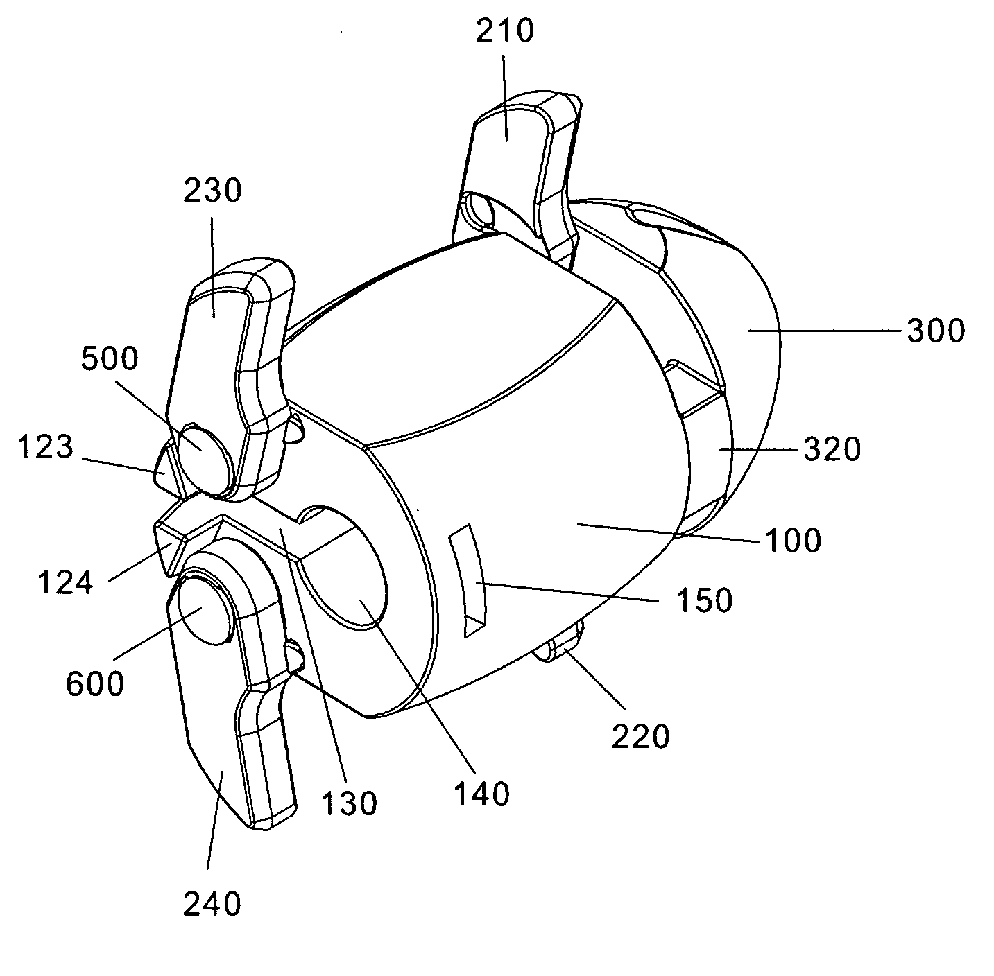
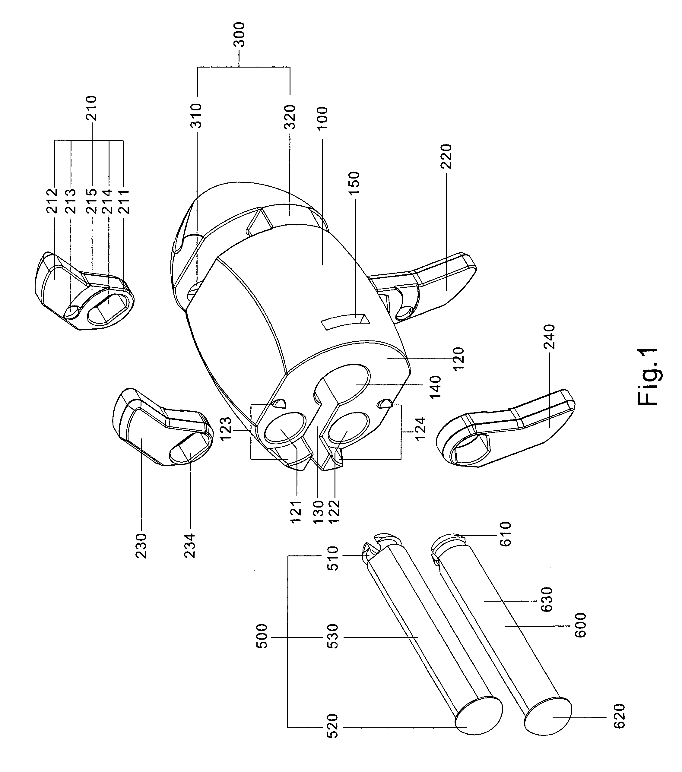
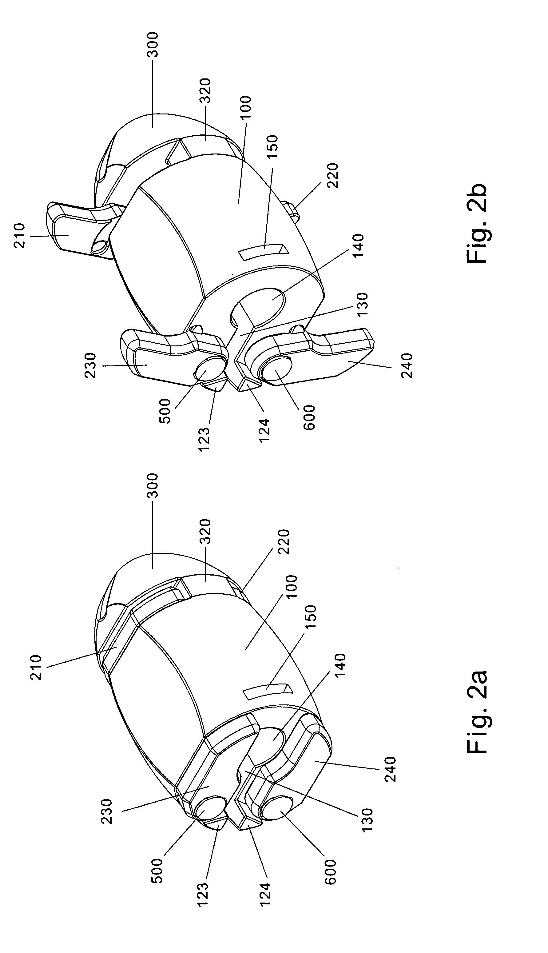
[0049]FIG. 1 is a perspective view that shows a disassembled interspinous spinal fixation apparatus according to a preferred embodiment of the invention, which comprises a main body 100. The main body 100 has a proximal end 120; a distal end opposite to the proximal end 120, which cannot be seen in FIG. 1 due to view angle; a third joining point 12 land a fourth joining point 122 of the proximal end 120; a first joining point and a second joining point of the distal end opposite to the third joining point 121 and a fourth joining point 122, which cannot be seen in FIG. 1 due to view angle; a third safeguard mechanism 123 and a fourth safeguard mechanism 124of the proximal end 120; a first safeguard mechanism and a second safeguard mechanism of the distal end opposite to the third safeguard mechanism 123 and the fourth safeguard mechanism 124, whic...


PUM


Abstract

An apparatus for interspinous spinal fixation is disclosed, which includes a main body having an end thereof as a distal end, and another end thereof as a proximal end, a cross section of the main body being of an annular or quasi-annular structure. A first joining point and a second joining point are provided at the distal end that are symmetric to each other relative to an opening of the annular or quasi-annular structure, while a third joining point and a fourth joining point are provided at the proximal end that that are symmetric to each other relative to the opening of the annular or quasi-annular structure. A first lateral piece, a second lateral piece, a third lateral piece, and a fourth lateral piece are joined with the first, the second, the third, and the fourth joining points of the main body, such that the first and the second lateral pieces can rotate axially about the first and the second joining points, thereby rotating from a folded position on the main body to an extended position; and the third and the fourth lateral pieces can rotate axially about the third and the fourth joining points, thereby rotating from a folded position on the main body to an extended position.

Description

FIELD OF THE INVENTION[0001]The invention relates to an apparatus for stabilizing the human spine, and more particularly to a spinal fixation apparatus to be inserted between neighboring vertebrae.DESCRIPTION OF PRIOR ART[0002]Spinal diseases, disorders of the facet joint and related tissues surrounding the spine are often accompanied by severe pain, and such disorders are frequently caused by several factors, which include the degeneration and aging of spinal discs. Moreover, the disorders may further evolve into more serious symptoms like dislocation or herniation of vertebrae. Consequently, any minor movements between the neighboring vertebrae can cause severe pain to an afflicted person while moving around.[0003]Spinal fixation apparatuses to be inserted between vertebrae has been introduced before, including patents like TW-590756, TW-00520986, and TW-00542712; in which a tether was used to securely hold a spinal fixation apparatus between the spinous process and the interspino...

Claims


Application Information

Patent Timeline
Patent Type & Authority Applications(United States)
IPC IPC(8): A61B17/70
CPCA61B17/7065
Inventor CHUANG, FONG-YINGKHOO, KRISTINE M.
Owner CHUANG FONG YING
Why Eureka
Try Eureka